RoboticSith
New member
Hello,
I'm working on a fairly complex project based on a Teensy4.0. I have a GPS module, a DS3231 RTC, a CAN transceiver, Level shifter, and local 20x4 character display all connected. This is designed to be a sort of master clock, the GPS is source A (primary) and the RTC is source B (secondary). It displays the current time, date, timezone, daylight savings and GPS details on the local 20x4 char LCD and transmits much of this data out on a CAN bus as message 0x001. This will eventually be connected to several downstream devices which will use the time data. There are essentially 5 states of operation even though it is not necessarily running as a state machine.
State1: GPS only
State2: RTC only
State3: GPS & RTC (using GPS since its considered the primary)
State4: Transition to RTC (when GPS data is lost)
State5: Transition to GPS (when GPS data is restored)
Everything except the GPS parsing (asynchronous UART) is run at a periodic rate of 1hz controlled by an output pin on the DS3231. This is connected to an interrupt on D6.
I'm running into a really strange issue where all the states work correctly (tested for several hours at a time) except state5. Both clock sources work perfectly independently and together, and the transition from GPS to RTC works (tested by grounding the EN line on the GPS module). Once I re-enable the GPS however, I get exactly 5 printouts to the monitor and then everything just stops... I know my main interrupt sequence is no longer running because the screen stops updating and my check battery LEDs no longer respond when I connect the sense lines to 3.3V. Hoping someone here can help me figure out what is going on.
Thus far, I encountered something in the Arduino reference library saying that you can't do certain things inside an interrupt (such as Serial and analogRead). There are clearly some exceptions to this since, with the exception of state 5, I am doing both Serial and analogRead commands every 1Hz sequence without issue. I'm wondering if the Serial line is somehow messing with the interrupts when GPS data returns and starts transmitting on a formally inactive bus.
Hardware Specifics:
Teensy4.0
GPS Module = https://www.adafruit.com/product/746
RTC Module = https://www.adafruit.com/product/3013
Display = https://www.adafruit.com/product/498
Display Backpack (i2c mode) = https://www.adafruit.com/product/292
Level Shift = https://www.sparkfun.com/products/12009
CAN Transceiver (S08 package)= https://www.nxp.com/part/TJA1049TK#/
Using Arduino 1.8.13 on Windows 10.
Library details:
"Wire.h" = Arduino standard
"SPI.h" = Arduino Standard
"Adafruit_LiquidCrystal_HW.h" = Adafruit library for controlling char LCDs using I2c/SPI and their 'backpack' module. I added HW SPI to it, hence "_HW"
"Adafruit_GPS_Custom.h" = Adafruit library for their GPS modules. I commented out some parts I was not using (SPI & I2C GPS modules) to save memory before moving to Teensy.
"FlexCAN_T4.h" = installed with Teensyduino.
"RTCLib_Custom.h" = Adafruit library for the DS3231. I added logic so it would use Wire1 on Teensy4.0.
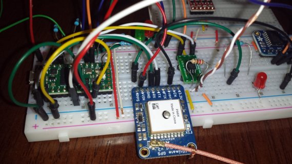
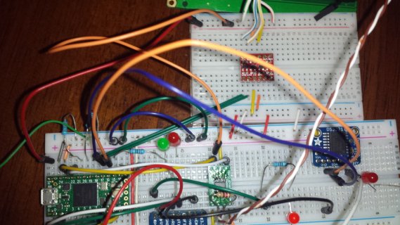
I don't have a schematic atm since this is a continuously evolving project (it exists, but only in my head as a fluid and continuously changing entity). The top 20ish lines of the code are a connection matrix. I can create a schematic if necessary, but it won't be instantaneous.
Breadboard Pictures are attached.
Code is also attached (Arduino .ino).
Thanks in advance.
I'm working on a fairly complex project based on a Teensy4.0. I have a GPS module, a DS3231 RTC, a CAN transceiver, Level shifter, and local 20x4 character display all connected. This is designed to be a sort of master clock, the GPS is source A (primary) and the RTC is source B (secondary). It displays the current time, date, timezone, daylight savings and GPS details on the local 20x4 char LCD and transmits much of this data out on a CAN bus as message 0x001. This will eventually be connected to several downstream devices which will use the time data. There are essentially 5 states of operation even though it is not necessarily running as a state machine.
State1: GPS only
State2: RTC only
State3: GPS & RTC (using GPS since its considered the primary)
State4: Transition to RTC (when GPS data is lost)
State5: Transition to GPS (when GPS data is restored)
Everything except the GPS parsing (asynchronous UART) is run at a periodic rate of 1hz controlled by an output pin on the DS3231. This is connected to an interrupt on D6.
I'm running into a really strange issue where all the states work correctly (tested for several hours at a time) except state5. Both clock sources work perfectly independently and together, and the transition from GPS to RTC works (tested by grounding the EN line on the GPS module). Once I re-enable the GPS however, I get exactly 5 printouts to the monitor and then everything just stops... I know my main interrupt sequence is no longer running because the screen stops updating and my check battery LEDs no longer respond when I connect the sense lines to 3.3V. Hoping someone here can help me figure out what is going on.
Thus far, I encountered something in the Arduino reference library saying that you can't do certain things inside an interrupt (such as Serial and analogRead). There are clearly some exceptions to this since, with the exception of state 5, I am doing both Serial and analogRead commands every 1Hz sequence without issue. I'm wondering if the Serial line is somehow messing with the interrupts when GPS data returns and starts transmitting on a formally inactive bus.
Hardware Specifics:
Teensy4.0
GPS Module = https://www.adafruit.com/product/746
RTC Module = https://www.adafruit.com/product/3013
Display = https://www.adafruit.com/product/498
Display Backpack (i2c mode) = https://www.adafruit.com/product/292
Level Shift = https://www.sparkfun.com/products/12009
CAN Transceiver (S08 package)= https://www.nxp.com/part/TJA1049TK#/
Using Arduino 1.8.13 on Windows 10.
Library details:
"Wire.h" = Arduino standard
"SPI.h" = Arduino Standard
"Adafruit_LiquidCrystal_HW.h" = Adafruit library for controlling char LCDs using I2c/SPI and their 'backpack' module. I added HW SPI to it, hence "_HW"
"Adafruit_GPS_Custom.h" = Adafruit library for their GPS modules. I commented out some parts I was not using (SPI & I2C GPS modules) to save memory before moving to Teensy.
"FlexCAN_T4.h" = installed with Teensyduino.
"RTCLib_Custom.h" = Adafruit library for the DS3231. I added logic so it would use Wire1 on Teensy4.0.
I don't have a schematic atm since this is a continuously evolving project (it exists, but only in my head as a fluid and continuously changing entity). The top 20ish lines of the code are a connection matrix. I can create a schematic if necessary, but it won't be instantaneous.
Breadboard Pictures are attached.
Code is also attached (Arduino .ino).
Thanks in advance.