Hi all-
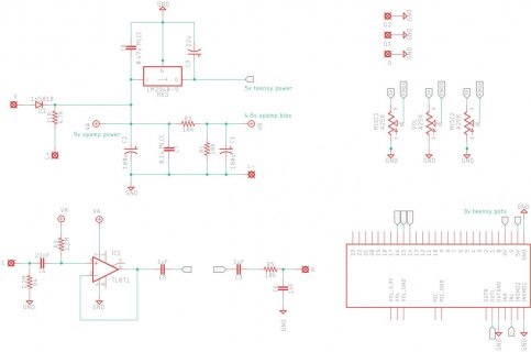
I've been playing with a simple PCB layout to provide a buffered input for guitar signals into the Teensy 4.0 & Audio Shield, and a few pots for experimentation. This board runs off 9vdc power (like most guitar pedals) and uses a regulator to produce 5v to power Teensy.
My Teensy part is from the Teensy_Audioshield eagle library (which I really appreciate!). I have line in/out connected between Audio Shield<->PCB with very short wires, since those signals don't appear on the pins. (right?) This means I can't pop the Teensy out of the 28-pin socket I soldered in, but I didn't have any other clever ideas.
What I have works fine but there's some audible HF noise / whine, particularly if the output goes into lots of of gain. I'd like to understand and fix that.
I'm pretty new to this stuff. I don't know if the regulator itself separates analog/digital power enough to keep things clean, and I haven't done anything yet to separate audio/digital grounds - the PCB has one big ground plane that everything is connected to. I realize these issues may cause noise. But...
Before I dive into improving my PCB layout, just wondering if there's any red flags in the way I'm using/wiring up the Audio Shield or its Eagle library part. AFAICT all the ground pins are the same (unlike AGND in 3.x) so only one GND pin needs to be grounded, and then I believe the audio in & out grounds should be wired too.
Schematic & code attached.
Thanks!

code: View attachment teensy_audio_test.cpp
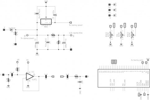
I've been playing with a simple PCB layout to provide a buffered input for guitar signals into the Teensy 4.0 & Audio Shield, and a few pots for experimentation. This board runs off 9vdc power (like most guitar pedals) and uses a regulator to produce 5v to power Teensy.
My Teensy part is from the Teensy_Audioshield eagle library (which I really appreciate!). I have line in/out connected between Audio Shield<->PCB with very short wires, since those signals don't appear on the pins. (right?) This means I can't pop the Teensy out of the 28-pin socket I soldered in, but I didn't have any other clever ideas.
What I have works fine but there's some audible HF noise / whine, particularly if the output goes into lots of of gain. I'd like to understand and fix that.
I'm pretty new to this stuff. I don't know if the regulator itself separates analog/digital power enough to keep things clean, and I haven't done anything yet to separate audio/digital grounds - the PCB has one big ground plane that everything is connected to. I realize these issues may cause noise. But...
Before I dive into improving my PCB layout, just wondering if there's any red flags in the way I'm using/wiring up the Audio Shield or its Eagle library part. AFAICT all the ground pins are the same (unlike AGND in 3.x) so only one GND pin needs to be grounded, and then I believe the audio in & out grounds should be wired too.
Schematic & code attached.
Thanks!

code: View attachment teensy_audio_test.cpp


