Hello clever folk
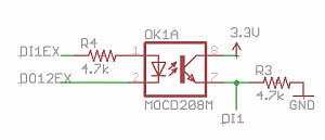
I found an opto isolator circuit online, and have used it before in my circuits for inputting 12v to my projects (circuit attached).
This circuit (according to the thread where I found the circuit), was good for an input of 5v - 24v DC
However, it's not. It doesn't trigger the MOCD208 until 5.6v input. I need that to be 5v.
I changed the pull-down resistors to 10k (from 4k7) and that appears to have fixed the issue. But, its all a bit 'stab in the dark'. At 53 years old, I still have not figured out how you calculate all this stuff.
The MOCD208 has a forward voltage of 1.55v and a max current of 60mA. What will this circuit achieve with the 4k7 changed to a 10k? The input spec is surely still the same, it's just easier to reach the input threshold of the Teensy.
I have tried working it out, but my brain melted.
There is probably a much better way of achieving this input isolation, but this circuit is now part of my etch board, so I have to live with it. Maybe version 2 can have a better design.
The opto-isolator worked fine on my breadboard pre-build, so I didn't think any more about it.
Can anyone tell me the min/max voltage this circuit can accept (and ideally, how you worked that out), and maybe any suggestions for better value resistors?
Thank you