MKL02 not starting up

Status
Not open for further replies.

jensa

Well-known member
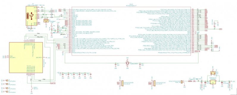
I just received 3 boards from PCBA that do not work at all and this is a curious case. The board is based on Teensy 3.2 and has a MKL02 from PJRC. This is version two of the board. The first version worked without a single issue. This one does not wake up, but the design is the same. The crystal, decoupling caps, mcu, mkl02 are all in the same place. The crystal is surrounded with a stitched ground plane, so no signals go across it. All 3V3 pins on both chips show good and clean voltage.

The MK20 is blank, so the MKL02 should pulse the RESET_B pin by default as mentioned here, but it just stays high (3V3). From what I can find on the forum, this should indicate that the MKL02 is good and up and running? The Program button connected to PTB2 also measures 3V3.

PTA6 = 3V3
PTA7 = GND
PTB0 = GND
PTB1 = 3V3

Pins not used by MKL02 measure PTA2 & PTA3 = 3V3, all others are GND. On a board that is working, the PTA6 & PTA7 will show a data signal. On the defect boards, these two pins are just steady at the same voltages.

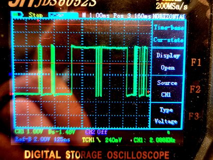
Pressing the Program button produces a pulse train on PTA7 (see attached scope picture), but then nothing happens. This makes me believe that something is wrong with my crystal or caps. I have now moved a known good crystal & caps from a different board without any change in result. I have also tried swapping both the MKL02 and MK20 with no change. I'd appreciate it if anyone could help me with what to do next, as I'm really stuck for now... Are there any pins that should not be used?

(I just realised that the topic is wrong. The MKL02 is starting up, but the MK20 does not)


Screenshot 2020-12-07 at 14.23.17.jpg
Screenshot 2020-12-07 at 14.27.23.jpg
pulse_train_IMG_20201207_151134.jpg
 
If you press and hold the button, so Program remains shorted to GND, what happens on Reset?

What's supposed to happen is for the MKL02 to hold Reset low while you keep Program low. If it's doing that, you can be pretty sure the MKL02 is still running.
 
The RESET is LOW when the Program button is held LOW, so I guess that confirms that the MKL02 is good. Also - since I see the pulse train on PTA7, it's trying to wake the MK20, but this fails.
Any pointers as to how to troubleshoot that?
 
You should have a decoupling capacitor on every MK20 3.3V line, close to the MK20 pin.

Which of these is the case?

a) MK20 is loaded and running, just not talking to USB
b) MK20 doesn't start up and keeps resetting itself
 
@jonr All power pins have a 0.1uF decoupling cap and one of them have a 10uF. The crystal is not resonating, so the MK20 does not start. How can I test if it tries to reset itself or is even responding at all?
 
Last edited:
When Program & Reset are good, but the crystal doesn't start up, usually that's a sign of problems with the 3 wires between the chips (PTA7, PTB0, PTB1 on the MKL02/04 chip). The 4th wire (PTA6 on the MKL02/04 chip) is not used, so you can ignore that one.
 
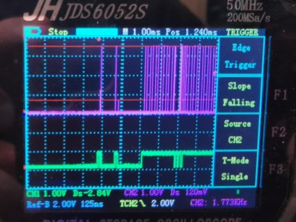
When I hit the Program button, a clock signal is produced on PTB0 on the MKL02 and I see data on PTA7 as expected. But this capture of the two channels is a bit surprising? The data channel is only 1 volt peak to peak, but the clock is 3V3 (as expected). I've probed to see if there are any shorts, but none of these pins have any contact to other pins. The resistance from each trace between the tiny solder blobs on the side MKL02 QFN and the MK20 pins is 0.3 ohm, so that shouldn't be a problem.

I think this voltage drop is part of the problem. What is the "Threshold voltage" for "logic high" on Teensy 3.2? I looked in the mk20dx256vlh7 datasheet and I can only find a number for the USB pins (0.8V)?


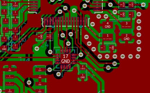
IMG_20201207_231702.jpg
 
Last edited:
Could be a short elsewhere.

As I see it, your power pin next to D4 goes to a via - not a decoupling capacitor.
 
The data channel is only 1 volt peak to peak

That's definitely not right. It should be 3.3V logic, just like the other signal.

Since you are seeing only 1V, it's probably shorted to something else which is trying to drive logic low.
 
It could be @jonr, but as mentioned - the previous version of this board had 100% identical layout on everything related to the Teensy. This board worked without any issues on all 3 copies I made, so I don't think a single missing cap is the reason here given that all three of the next batch fails here? That is - I do actually have more pins hooked up on this version so more capacitance might be required... I'll add that cap and also try to lift some pins to see if that helps.

@PaulStoffregen This post has a great overview of the sequencing on the Mini54Tan http://www.appfruits.com/2015/03/building-your-own-custom-teensy/ From what I understand, the sequencing for MKL02 is identical? Is there a writeup that you know of that covers what happens after the point that I have gotten? It would be great to have a full list like that when debugging things like this.
 
Is there a writeup that you know of that covers what happens after the point that I have gotten?

Everything I have written is on that MKL02 page and threads on this forum.


It would be great to have a full list like that when debugging things like this.

Nice as that might be, it's pretty clear you've found the problem. That data signal is supposed to be 3.3V logic. A 1V signal isn't going to work.

Now you just need to put in the extra work to go from "what" to "why". I believe you should stop assuming your design is perfect because previous boards worked. They too could have had a logic conflict, but perhaps whatever pulls the signal down to 1V was not quite as strong with the parts you used before, perhaps allowing just barely enough voltage to work.

Or this could be just a simple as a solder bridge or PCB defect shorting signals together. Of course I'm just guessing. I don't really know why you're seeing only 1V on that signal. But I do know it should be 3.3V. Something is very wrong it you're only getting a little less than 1/3rd of the correct signal voltage!

When you do figure out why it's not the proper logic levels, I hope you'll share that finding. Later others are likely to find this thread if they have a similar problem. While a lengthy write-up on how everything works would be nice, just sharing a few words with the gained knowledge & experience of what caused than erroneously low 1V signal could really help someone else in the future.
 
It's common in electronics and many other fields: "X worked once, so X is good practice".
 
Solved it!
The 1V signal was fixed by reflowing the MKL02 and when this did nothing and all else looked good, I got annoyed and started removing IC's one by one while testing. After removing 8 ICs with hot air, I finally found the culprit. I have an optocoupler on this board that I'm using for the first time and I've not used the correct pinout (mismatch with schematic symbol / footprint in my Kicad file).

On the other two boards I could just remove this single component and the boards came up as they should have initially. So I guess I learned that if all looks good, the error might totally be anywhere else in the circuit? Thanks for all your help debugging this!
 
Status
Not open for further replies.
Back
Top