Teensy 4.0 and CAN using SN65HVD230

Hello everyone. I'm having trouble switching from 5V to 3.3V logic for CAN transceivers. I'm currently using MCP2551s but the 'problem' is that it needs a lot of cabling as I need to drive the voltage down using logic converters. And so I've decided to use a SN65HVD230. I've built up my testing rig and .... *pfffff*. Nothing. I've set up my Teensy 4.0 to use two CAN controllers CAN 1 and CAN 2 (I'm actually driving three but I don't thing that matters here). CAN 2 is connected to the MCP2551 via a logic converter and the SN65HVD230 is connected to CAN1.
I connect a CAN-2-USB converted to a PC and see if I'm receiving a message.
Teensy creates an identical message for both buses with the exception that CAN 1 has a message with ID=1 and CAN 2 has a message with ID=2.
When reading CAN buses I can see CAN 2 messages but not CAN 1.
Can someone tell me what am I doing wrong? Maybe it has something to do with the library? I'm using a FlexCAN_T4. Maybe I've screwed up my connections? Or maybe the SN65HVD230 just doesn’t play well with Teensy 4.0, though I think I did see examples of people getting it to work.
If anyone could help me, I'd appreciate it.

Cheers,
Rafał Typiak


Code below
Code:
#include <FlexCAN_T4.h>


FlexCAN_T4<CAN1, RX_SIZE_256, TX_SIZE_16> myCan1;
FlexCAN_T4<CAN2, RX_SIZE_256, TX_SIZE_16> myCan2;
FlexCAN_T4<CAN3, RX_SIZE_256, TX_SIZE_16> myCan3;

void setup() {
  // put your setup code here, to run once:
myCan1.begin();
myCan2.begin();
myCan3.begin();
myCan1.setBaudRate(250*1000);
myCan2.setBaudRate(250*1000);
myCan3.setBaudRate(250*1000);
}

void loop() {
  // put your main code here, to run repeatedly:
CAN_message_t msg;
msg.len=8;
msg.id=1;
msg.buf[0]=1;
msg.buf[1]=2;
msg.buf[2]=3;
msg.buf[3]=4;
msg.buf[4]=5;
msg.buf[5]=6;
msg.buf[6]=7;
msg.buf[7]=8;

myCan1.write(msg);
msg.id=2;
myCan2.write(msg);
msg.id=3;
myCan3.write(msg);
 delay (500);

}

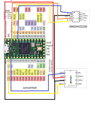
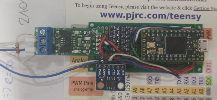
Connection diagram below

schemat.png
schemat2.png
 
Last edited:
toggle a led in your loop() to make sure the loop() is still running, also check your CAN lines are terminated
 
toggle a led in your loop() to make sure the loop() is still running, also check your CAN lines are terminated

I could do that but I don't think that's necessary as I know that the loop is running. I am getting CAN messages on CAN 2, just not CAN 1. I'm reading from both at the same time.
I've modified my board a bit by adding goldpins on Teensy's Rx and Tx for CAN 1 and CAN 2. During operation I've switched between both bus controller outputs and found that the MCP2551 can read data coming from both controllers. It outputs ID 1 frames when connected to CAN 1 and ID 2 frames when connected to CAN 2. The SN65HVD230 - nothing.

Also you may wanna look at the first post here:
https://forum.pjrc.com/threads/51870...30-transciever!

I've also taken a look at the post you've shown but haven't found anything useful there. I've tried several libraries so far, but the one by teachop is sadly for Teensy 3.2. I haven't found any info on T4.0 support.
If anyone else has any ideas, I'd be grateful.

Cheers,
Rafał Typiak
 
Note alot of google results show issue with your transceiver. I am using all 3 CAN busses in my project. One of the issues explained in that post is that transceiver being able to receive but not transmit. If there is an issue with transmit then there can be no ACK, and thus, you will not receive a frame
 
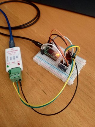
Made a quick setup using a Teensy 4.0 and 2 of those cheap TI SN65HVD230 CAN-bus transceiver modules.
This is the setup:

IMG_20210107_121346.jpg
I connected the CANL & CANH signals from both transceivers to a CANbus analyzer [the yellow & green wires].

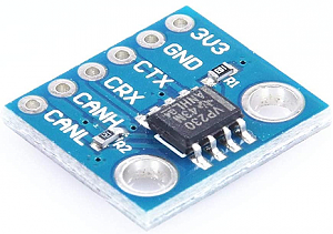
This is the transceiver module:

TI SN65HVD230 CAN-bus transceiver module.png

With this code...
Code:
// https://forum.pjrc.com/threads/65733-Teensy-4-0-and-CAN-using-SN65HVD230

#include <FlexCAN_T4.h>

FlexCAN_T4<CAN1, RX_SIZE_256, TX_SIZE_16> myCan1;
FlexCAN_T4<CAN2, RX_SIZE_256, TX_SIZE_16> myCan2;
FlexCAN_T4<CAN3, RX_SIZE_256, TX_SIZE_16> myCan3;

void setup() {
  // put your setup code here, to run once:
  pinMode(LED_BUILTIN, OUTPUT);          // added to show loop() activity 
  myCan1.begin();
  myCan2.begin();
  myCan3.begin();
  myCan1.setBaudRate(250 * 1000);
  myCan2.setBaudRate(250 * 1000);
  myCan3.setBaudRate(250 * 1000);
}

void loop() {
  // put your main code here, to run repeatedly:
  digitalToggle(LED_BUILTIN);          // added to show loop() activity 
  CAN_message_t msg;
  msg.len = 8;
  msg.id = 1;
  msg.buf[0] = 1;
  msg.buf[1] = 2;
  msg.buf[2] = 3;
  msg.buf[3] = 4;
  msg.buf[4] = 5;
  msg.buf[5] = 6;
  msg.buf[6] = 7;
  msg.buf[7] = 8;

  myCan1.write(msg);

  msg.id = 2;
  myCan2.write(msg);

  msg.id = 3;
  myCan3.write(msg);
  delay (500);
}

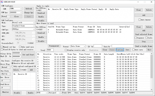
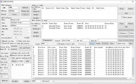
... I saw this on the CAN bus analyzer:

CANanalyzer.png

The bottom-right window shows the frames with alternating frameIDs and correct timing.

So the cheapo transceivers seem to work well with Teensy 4 and the FlexCAN_T4 library. I guess you need to dig into the MCP2551-based transceiver and its wiring.

Regards,
Paul
 
Hi guys,
sorry for the delay but COVID makes things so hectic at work that it's hard to find the energy for anything more.
So I've tried a new setup and I still keep failing.
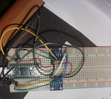
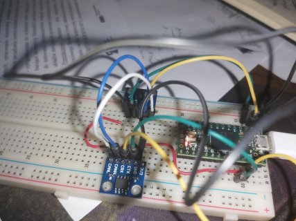
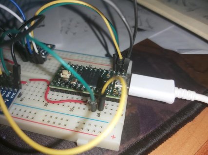
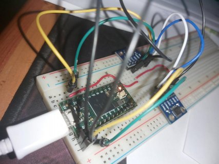
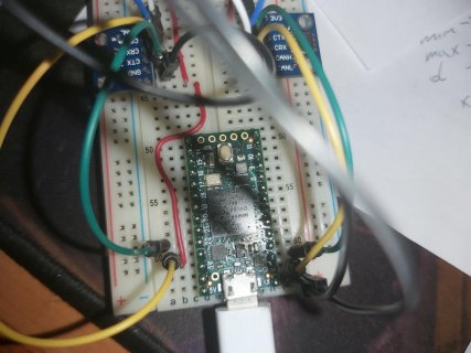
Here's my new setup. It's a completely new Teensy (the transceivers are the same).
20210113_134250.jpg
20210113_134256.jpg
20210113_134301.jpg
20210113_134310.jpg
20210113_134320.jpg

I've used the following code:
Code:
#include <FlexCAN_T4.h>


const int ledPin = 13;

FlexCAN_T4<CAN1, RX_SIZE_256, TX_SIZE_16> myCan1;
FlexCAN_T4<CAN2, RX_SIZE_256, TX_SIZE_16> myCan2;
FlexCAN_T4<CAN3, RX_SIZE_256, TX_SIZE_16> myCan3;

void setup() {
  // put your setup code here, to run once:
  Serial.begin(9600);
  pinMode(ledPin, OUTPUT);
  
myCan1.begin();
myCan2.begin();
myCan3.begin();
myCan1.setBaudRate(250*1000);
myCan2.setBaudRate(250*1000);
myCan3.setBaudRate(250*1000);

}

void loop() {
  // put your main code here, to run repeatedly:
CAN_message_t msg, rmsg;
msg.len=8;
msg.id=1;
msg.buf[0]=1;
msg.buf[1]=2;
msg.buf[2]=3;
msg.buf[3]=4;
msg.buf[4]=5;
msg.buf[5]=6;
msg.buf[6]=7;
msg.buf[7]=8;

myCan1.write(msg);
msg.id=2;
myCan2.write(msg);
msg.id=3;
myCan3.write(msg);

 if ( myCan1.read(rmsg) ) 
 {
 Serial.print("CAN1 "); 
 Serial.print("  ID: 0x"); Serial.print(rmsg.id, HEX );
 }
 if ( myCan2.read(rmsg) ) 
 {
 Serial.print("CAN2 "); 
 Serial.print("  ID: 0x"); Serial.print(rmsg.id, HEX );
 }
 Serial.println ("Hi!");

digitalWrite(ledPin, !digitalRead(ledPin));
delay (500);
}

Neither controller returns a message information.
What am I doing wrong? Can it be the library? I know that this library works with the MCP2551 unit as I was able to send CAN data from a PC to Teensy using this lib.
Wiring seems ok. I've used full rod cables previously but have switched to those seen in the photos as the original ones weren't colour coded.

Do I need to take out the oscilloscope? If so what should I be looking for? Should data transfers bee only visible on Tx when there are no CAN_L and CAN_H cables connected?

Thanks for any help you can spare.

Cheers,
Rafał Typiak
 
Hi Rafal,

Saw from the photo's that you copied my setup, good, than we have the same setup hardware-wise. Your wiring seems to be OK.
Ran your code from message #7 and everything seems to be working well!?
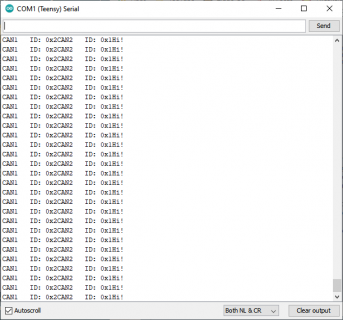
Here is the serial output:

Serial.png

and the CAN analyzer output:

CANanalyzer.png

What version Arduino/Teensyduino are you running? I'm on Arduino 1.8.13, Teensyduino 1.53.
Teensyduino 1.53 comes with the latest FlexCAN_T4 library. Is there perhaps an other/older FlexCAN_T4 library in your C:\Users\xxxx\Documents\Arduino\Libraries\ folder?

Using a scope, you should see activity on the CTX & CRX pins. And on the CANL & CANH lines.

Regards,
Paul
 
Hi,
thanks for your help.
Yup. I wanted to recreate your setup to check why I'm failing. My Arduino is at: 1.8.13 and Teensyduino is as 1.53. I guess the first step will be to update that.
I do also have an additional FlexCAN_T4 lib in Documents. So.... yeah..... I'll see if getting those two sorted out would change stuff.

Thanks again!

Cheers,
Rafał Typiak
 
You're welcome.
No need to update Teensyduino 1.53, that is the latest.
Yes, please delete any FlexCAN_T4 libraries under Documents\Arduino\Libraries\ to make sure you're using the one that came with Teensyduino. Which should be located here: C:\Program Files (x86)\Arduino\hardware\teensy\avr\libraries\.

Paul
 
Hi

I found this thread very useful for setting up CAN 2.0 communication. I am struggling however to set up can FD using this library and the same components. In the FlexCAN_T4 library there aren't any examples for CAN FD, does anyone have an example that they know that works I can use to double-check my code, please?

Thanks
 
You're welcome.
No need to update Teensyduino 1.53, that is the latest.
Yes, please delete any FlexCAN_T4 libraries under Documents\Arduino\Libraries\ to make sure you're using the one that came with Teensyduino. Which should be located here: C:\Program Files (x86)\Arduino\hardware\teensy\avr\libraries\.

Paul

Hi I have the same setup but with a teensy 4.1 and using 2.0.4 with teensy1.57.2 I can't get it to receive any of the signals from the canbus. I would upload pictures but I get an error when I attempt to do so
 
Hello, were you able to figure out the problem? We have hooked up our can lines to an oscillascope and even when we are trying to transmit a can message both lines read a nominal value of 0. We have checked all of the solder points and they are all hooked up well. We have wired up a teensy 4.1 in the same way you have your 4.o wired up in the image. Any help would be appreciated. We are using the code that you posted, copied and pasted
 
Hi I have the same setup but with a teensy 4.1 and using 2.0.4 with teensy1.57.2 I can't get it to receive any of the signals from the canbus. I would upload pictures but I get an error when I attempt to do so
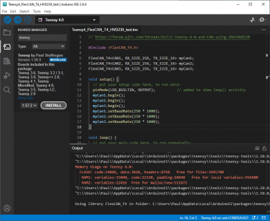
Just ran the code from my message #6 above, using the exact same hardware, but this time compiled with ArduinoIDE 2.0.4 & Teensyduino 1.58.0:

Untitled.png

Program runs fine and shows the same on the CAN Analyzer.
Please double-check your wiring and perhaps swap CAN transceiver modules?

Paul
 
No Capacitor in the circut?

Hey guys,

I just go my setup to work in the same setup that Rafal had in post #7. I originally had a capacitor on each of the transceiver lines to function as a bypass capacitor. When I did this - the circuit wasn't working. Does anyone know why? I thought these were important because in any switching circuit, like this CAN transceiver, every time it switches it's going to draw a big burst of current and cause a voltage drop all the way back on the line to the power source. Adding a capacitor instead will draw current from the capacitor rather than the supply. Voltage drop is then localized around the chip.
 
I originally had a capacitor on each of the transceiver lines to function as a bypass capacitor
By transceiver lines you mean CTRX & CRX or CANH & CANL? Anyway, these lines should not have a bypass capacitor at all. If you want to add a bypass capacitor a.k.a decoupling capacitor, you should place that cap at the 3V3 powersupply pin of the CAN module.

Paul
 
By transceiver lines you mean CTRX & CRX or CANH & CANL? Anyway, these lines should not have a bypass capacitor at all. If you want to add a bypass capacitor a.k.a decoupling capacitor, you should place that cap at the 3V3 power supply pin of the CAN module.

Paul

Yes, I did mean through the 3.3v power supply. I was able to get it to function once I restructured my circuit. I am also curious as to why a 120ohm terminating resistor isn't needed in between the CANH & CANL lines. Is it because this system only has 2 transceivers and there isn't much interference happening to the system because of its size?

I was trying to find a data sheet on the cheap SN65HVD230 transceivers to see if that was included internally but wasn't able to find anything. From my understanding, the 120 ohm terminating resistor is needed to be able to read the low-level signal when there are larger CAN lines in play. Here is an article about it: https://www.csselectronics.com/prod...,interference and potentially damaged signals
 
If you look closely at the photo of the CAN transceiver module in message #6, you can see resistor R2 which has "121" printed on it, meaning 120Ω.
So a terminating resistor is actually present.

Paul
 
Back
Top