
Hi, i found a nice schematic for a over-voltage protection circuit when using 3.5mm connectors for midi, as users might plug cv and gate(+-12v) in accidentally
The schematic/discussion can be found here: https://electronics.stackexchange.com/a/423181/273704
after some doing some measuring i cant see any signal after the diode:

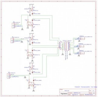
Here is my own schematic:

Could i be using the wrong type of transistors, or inverter? should i change the resistors as im using 3.3v instead of 5v as in the original schematic?
Im using the midi out example code from here: https://www.pjrc.com/teensy/td_libs_MIDI.html
I have tried to bypass the protection circuit and that makes the midi work.
(Another problem i have encountered is that when plugging the cable in and out i causes the device i'm sending to, to stop receive the midi messages, and need to reboot the device to start receive again, might be the receiving device, need to test with something else to see where the problem lies)
The schematic/discussion can be found here: https://electronics.stackexchange.com/a/423181/273704
after some doing some measuring i cant see any signal after the diode:
Here is my own schematic:
Could i be using the wrong type of transistors, or inverter? should i change the resistors as im using 3.3v instead of 5v as in the original schematic?
Im using the midi out example code from here: https://www.pjrc.com/teensy/td_libs_MIDI.html
I have tried to bypass the protection circuit and that makes the midi work.
(Another problem i have encountered is that when plugging the cable in and out i causes the device i'm sending to, to stop receive the midi messages, and need to reboot the device to start receive again, might be the receiving device, need to test with something else to see where the problem lies)


")