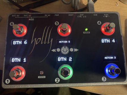
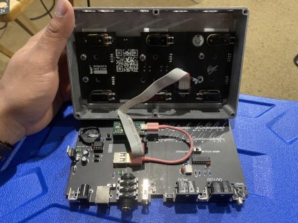
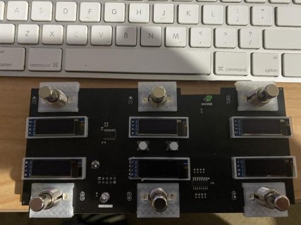
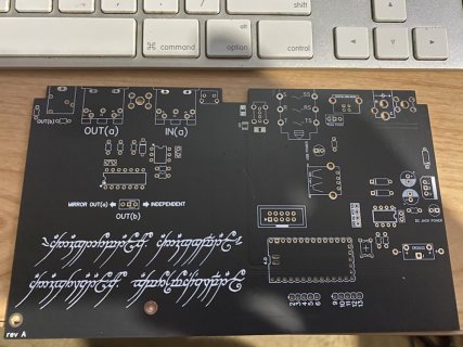
Hi all, I wanted to share my latest MIDI Project now that it's finished, it took a lot of engineering to get it all to properly fit in a 1590DD box specially with the OLED displays and keeping my teensy with header sockets. it's made from 2 boards, the top board holds the OLED displays and WS2812s along with footswitches, the bottom board holds the Teensy and all the IO and MIDI circuitry an it runs BMC (https://github.com/neroroxxx/BMC) out of the box.
As far as the hardware it uses:
12 x WS2812, 2 in parallel for each footswitch (only the output of one used to link to the next pair)
1 x 74HC165 for the 6 footswitches and the 2 tact buttons in the middle
6 x128x32 OLED displays (from amazon)
1x TCA9548A i2c multiplexer for the displays
1 x Status LED wired directly to a pin on the teensy
1 x TPD35014 for USB Host
1 x USB Host Jack for MIDI over USB Host
1 x Serial MIDI Input with H11L1
1 x Serial MIDI Output using Hex inverter
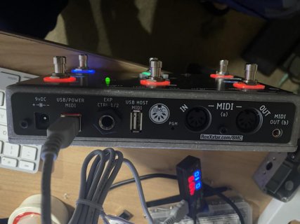
1 x 1/8" Serial MIDI Output which can either mirror the first MIDI Output or be an independent output
1 x DC Jack with 7508 for 9vDC input (can be powered either by USB or DC Jack or both at the same time)
1 x 2032 battery for time keeping
1 x 24LC256 for added EEPROM for BMC
1 x 1/4" TRS Switching Jack for expression/footswitch pedal
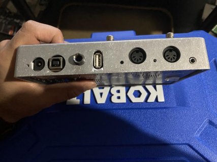
As you can see on the pictures I wanted to us a USB Type B jack not the micro usb jack as i've broken so many whe doing gigs so i had to use a USB cable inside the box and a USB Type A to link to the USB type B.
The IO board also has a right-angle tact switch which is connecte to the Program Pin of the teensy, this is so i can use a paper clip to put the teensy in program mode instead of taking the box apart to press the button, there's also an ON/OFF button on the board but i just put it there in case
Power from USB goes to a diode directly from the Type B jack but the usb cable inside doesn't take power from the Type B jack instead the Type B jack passes power to a pair of diodes to choose between the DC jack or USB power
The 2 boards are linked by an IDC cable, all the plastic hardware is 3D printed.
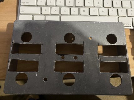
The hardest part wa designing both boards in parallel and making sure there's room between the 2 so they can fit, also using a dremel to cut those 3mm thick boxes was a big pain lol
The oleds display the action of each footswitch and other data temporarily, the 2 little tact buttons i use to switch between pages in BMC.
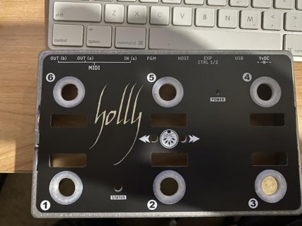
I designed 2 additional boards which i use one on the top of the box to cover imperfections and the other one covers the I/O jacks in the back again to cover imperfections.
It was a fun project that took about 4 months of design and testing but now that it's done i wanted to share it here.


Last edited:

