Introspector
New member
Hey Guys! I’m currently trying to use the teensy audio library to visually represent audio. The way I’m doing this is mapping the two stereo audio inputs to the position coordinates on an LED array(Left amplitude controls the x position, right amplitude controls the y position). I’m still trying to understand how to pull raw ADC values using the audio library. I tried setting up two queues (one for each stereo channel), then I'm continuously grabbing values from the queue. So, according to the audio library documentation, I can get the pointer location of the raw integer values coming from the ADC using the readBuffer() function. I try to do that in the code below.
I’m also not entirely sure if my hardware setup is working correctly. For this, I’m taking an audio input from my phone, running it through a preamp, then running it through the circuit that was detailed in the adcs section of the audio library. When I measure the DC value of either analog pin with a multimeter, it reads 0.604 Volts. My preamp gain is adjustable rn, but I can adjust the AC RMS voltage to be at around 400 mV, which is what I have it at now. I can make this bigger though. I’ve got everything on a PCB rn, and it seems like I’m getting an audio signal there. I’ve attached my schematics and code below.
My questions are as follows:
1. Am I correctly pulling data from these queue buffers?
2. Is my understanding of the form of the ADC data correct? Should the values range from 0-65536 depending on the voltage, and the voltage
range is between 0-1.2 Volts?
3. Is there a way to adjust this voltage range? Or am I stuck with this?
4. Are the values that I’m getting from the queue sensible values for both no audio and when audio is being played?
5. Does my hardware setup look correct?

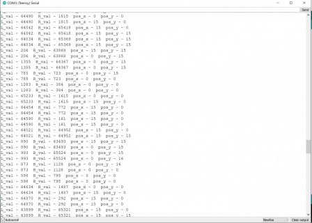
This is a log of the ADC values I'm getting when no audio is being played. This is very odd because I'm getting massive values when it should be sitting at about the halfway point. I would also think the value would stay relatively constant. Note that the two leftmost values are the ADC raw audio data from left and right channels

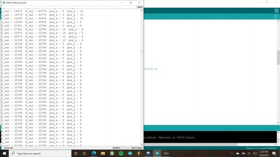
This is a snippet of the values when audio is being played through the audio jack
Here's my code:
and finally, my hardware schematic:

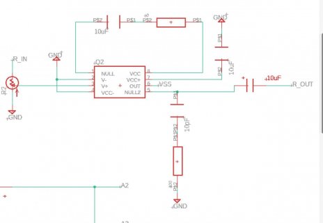
this is my preamp circuit. R_in is the right input of an audio jack. I'm using an LM358 op-amp. This circuit came from an amplifier prototype board I bought. There's an identical circuit for L_in as well.

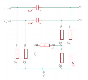
Here's the buffer circuit that was described in the documentation. This is fed directly into the teensy analog pins A2 and A3.
I’m also not entirely sure if my hardware setup is working correctly. For this, I’m taking an audio input from my phone, running it through a preamp, then running it through the circuit that was detailed in the adcs section of the audio library. When I measure the DC value of either analog pin with a multimeter, it reads 0.604 Volts. My preamp gain is adjustable rn, but I can adjust the AC RMS voltage to be at around 400 mV, which is what I have it at now. I can make this bigger though. I’ve got everything on a PCB rn, and it seems like I’m getting an audio signal there. I’ve attached my schematics and code below.
My questions are as follows:
1. Am I correctly pulling data from these queue buffers?
2. Is my understanding of the form of the ADC data correct? Should the values range from 0-65536 depending on the voltage, and the voltage
range is between 0-1.2 Volts?
3. Is there a way to adjust this voltage range? Or am I stuck with this?
4. Are the values that I’m getting from the queue sensible values for both no audio and when audio is being played?
5. Does my hardware setup look correct?

This is a log of the ADC values I'm getting when no audio is being played. This is very odd because I'm getting massive values when it should be sitting at about the halfway point. I would also think the value would stay relatively constant. Note that the two leftmost values are the ADC raw audio data from left and right channels

This is a snippet of the values when audio is being played through the audio jack
Here's my code:
Code:
#define NUM_COL 16
#define NUM_ROW 16
#define NUM_LED NUM_COL*NUM_ROW
#define LED_PIN 2
#define BRIGHTNESS  64
#define FPS 500
#define FFT_GRAN 173
#define LED_TYPE WS2812B
#define COLOR_ORDER RGB

#define MIN_BOUND 0
#define MAX_BOUND 65536

#define MID_BAND 3
#define HIGH_BAND 55

#include <FastLED.h>

#include <Audio.h>
#include <math.h>
#include <Wire.h>
#include <SPI.h>
#include <SD.h>
#include <SerialFlash.h>

// GUItool: begin automatically generated code
AudioInputAnalogStereo   adcs1;          //xy=158,283
AudioRecordQueue         L_Queue;           //xy=329,185
AudioMixer4              mixer1;         //xy=330,274
AudioRecordQueue         R_Queue;           //xy=330,381
AudioAnalyzeFFT256       fft256;       //xy=484,267
AudioConnection          patchCord1(adcs1, 0, mixer1, 0);
AudioConnection          patchCord2(adcs1, 0, R_Queue, 0);
AudioConnection          patchCord3(adcs1, 1, mixer1, 1);
AudioConnection          patchCord4(adcs1, 1, L_Queue, 0);
AudioConnection          patchCord5(mixer1, fft256);
// GUItool: end automatically generated code


int num_col = NUM_COL;
int num_rows = NUM_ROW;

float low_freq = 0;
float mid_freq = 0;
float high_freq = 0;
float rms1_val = 0;
float rms2_val = 0;

int pos_x = 0;
int pos_y = 0;

uint16_t min_bound = 0;
uint16_t max_bound = 65535;

float mid_thresh = 0.14;
float low_thresh = 0.14;
int mid_band_bin = MID_BAND/FFT_GRAN;
int high_band_bin = HIGH_BAND/FFT_GRAN;
uint8_t red = 0;
uint8_t green = 0;
uint8_t blue = 0;

CRGB leds[NUM_LED];


void setup() {
  AudioMemory(50);
  Serial.begin(9600);

  FastLED.addLeds<LED_TYPE, LED_PIN, COLOR_ORDER>(leds, NUM_LED).setCorrection( TypicalLEDStrip );
  FastLED.setBrightness(  BRIGHTNESS );
  delay(5000);
  L_Queue.begin();
  R_Queue.begin();
  delay(100);

}

void loop() {

  uint16_t (*buff_pointer_L) = (L_Queue.readBuffer());
  uint16_t (*buff_pointer_R) = (R_Queue.readBuffer());

 if((L_Queue.available() > 1) && (R_Queue.available() > 1)){

  for(int i = 0; i < 128; i++){

    //this conditional is to ensure that the ADC values are within the specified range
    if((*buff_pointer_L >= min_bound) && (*buff_pointer_L < max_bound)&&(*buff_pointer_R >= min_bound) && (*buff_pointer_R < max_bound)){
      pos_x = ampPosMap(*buff_pointer_L, NUM_COL);
      pos_y = ampPosMap(*buff_pointer_R, NUM_ROW);

      Serial.print("L_val - ");
      Serial.print(*buff_pointer_L);
      Serial.print("  ");
      Serial.print("R_val - ");
      Serial.print(*buff_pointer_R);
      Serial.print("  ");
      Serial.print("pos_x - ");
      Serial.print(pos_x);
      Serial.print("  ");
      Serial.print("pos_y - ");
      Serial.print(pos_y);
      Serial.println("  ");

    }
    buff_pointer_L++;
    buff_pointer_R++;
  }

  setLEDArray(255, 255, 255);    //setting to white for now

  FastLED.show();

  FastLED.delay(1000/FPS);//wait a period of time based on framerate

  //set same location to black
  setLEDArray(0, 0, 0);
  FastLED.show();
  L_Queue.freeBuffer();
  R_Queue.freeBuffer();

 }
}

void setLEDArray(uint8_t red, uint8_t green, uint8_t blue){
  if(pos_y % 2 == 0){
    leds[pos_y*NUM_COL + pos_x] = CRGB(red, green, blue);
  }
  else{
    leds[(pos_y+1)*NUM_COL - pos_x] = CRGB(red, green, blue);
  }
}

int ampPosMap(uint16_t aud, float num){
  uint16_t gran = (max_bound - min_bound)/num;
  int pos_init = 0;

  pos_init = getPos(aud, min_bound, (min_bound+gran), gran, pos_init, num);
  return pos_init;
}

int getPos(float aud, float gran_low, float gran_high, float gran, int pos_init, int num){

  if((aud <= gran_high) && (aud > gran_low)){
    return pos_init;
  }
  else if(gran_low < max_bound){
    return (getPos(aud, (gran_low + gran), (gran_high + gran), gran, (pos_init + 1), num));
  }
  else{
    return (getPos(aud, (gran_low + gran), (gran_high + gran), gran, (pos_init - num + 1), 0));;
  }
}
and finally, my hardware schematic:

this is my preamp circuit. R_in is the right input of an audio jack. I'm using an LM358 op-amp. This circuit came from an amplifier prototype board I bought. There's an identical circuit for L_in as well.

Here's the buffer circuit that was described in the documentation. This is fed directly into the teensy analog pins A2 and A3.

