Ili9341_t3n, speed tests and crappy cables.

joey120373

Well-known member
I started playing around with A T4 and the adafruit 2.8inch TFT with cap touch.

I am running the scroll demo in the examples folder, as I intend to build a “hyper term”
Like serial monitor that will also display other data about the incoming serial stream, having one port or of the screen scroll, while another part just updates text, this example code is a perfect starting point.

Using some 6 inch DuPont jumpers, I was able to get my SPI transmit clock to 60000000, and the same for the SPI read.

Happy with that, I called it a day. Next morning I started working on it again and it wouldn’t work, white screen of death as it were. I had to back the clock back to 40Mhz to get it working again.

So, I soldered the teensy to the display with just about as short a wire as I could, maybe 1.5 inches (40mm) or so.

What a difference that made! I am now running at 100Mhz on SPI write, and 70Mhz on read.

I am wondering if anyone else has played around with this and what rates they are getting?

Joe
 
The limiting factor is typically inductance - you ideally want to run a ground wire between every pair of signal wires to provide
low inductance return paths for each. Otherwise you'll get strong crosstalk between signals as the frequency goes up and signal
wires use the nearby signals as returns.
 
The limiting factor is typically inductance - you ideally want to run a ground wire between every pair of signal wires to provide
low inductance return paths for each. Otherwise you'll get strong crosstalk between signals as the frequency goes up and signal
wires use the nearby signals as returns.


That’s good advice. But I wonder how that might be done with a development board that has just a .100 header. Even if I were to roll my own board, and get the teensy SPI traces as short as possible to the ribbon connector, how would one accomplish this? The ribbon connector doesn’t appear to support this, it looks as though most of the ground connections are at one end, and the serial connections are nearer the middle. I would like to build such a board, with the SPI buss as optimal as possible. Solder the teensy directly to the board ( no pin headers ) and keep the traces well shielded and short. But outside of an un-interrupted ground fill I don’t see a way to accomplish this. I guess one could carry each ground signal back to the teensy ground pin and star it there, that would at least keep them somewhat separate. I’ll keep looking at the data sheet as time allows and see if there is any more info as to the ground paths.

Would adding some 74hc’s help the signal integrity or would it be better to go directly to the ili9341?

I’m thinking of a small board, with pin headers to access all the teensy pins, but get the SPI buss as good as can be done. A lipo circuit and lipo connector just because.
 
I have found in lots of cases the connections with many breadboards and with many jumper cables, does not always work that great. It usually works find for most things I end up doing.

After all I mainly just dink around with the different pieces.

The majority of the time, I usually keep it around 30mhz maybe up to 40mhz max.

One reason is if you look at the datasheet: https://www.pjrc.com/teensy/IMXRT1060CEC_rev0_1.pdf
Which if the same as the copy I have downloaded (Page 68)
Absolute maximum frequency of operation (fop) is 30 MHz. The clock driver in the LPSPI module for fperiph must be
guaranteed this limit is not exceeded.

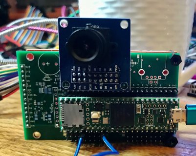
And so I took the lead from @FrankB and built a board the same size the ILI9488 (actually a few different ones) and does make it a lot easier to get everything to work...
Like the quick and dirty one I did that also had connection for an OV7670 camera... Again just for fun.

The main problem I usually run into, is usually end up with everything including the kitchen sink :D But it is fun!

IMG_1259.jpg
 
Yesterday tested the same display with this library. Just measured microsecond needed to display one string (about 25 characters long) on the screen. I was shocked with the results. It's about can bus debug.
Here is the code:
Code:
  microseconds_start = micros();
    tft.fillScreen(ILI9341_BLACK);
    sprintf(can_sendh,"H:%d:0x%08X:%02X%02X%02X%02X%02X%02X%02X%02X", msg.len, msg.id,msg.buf[0],msg.buf[1],msg.buf[2],msg.buf[3],msg.buf[4],msg.buf[5],msg.buf[6],msg.buf[7]);
    tft.drawString(can_sendh, 160, 120);
    Serial.println(micros()-microseconds_start);

With tft.fillScreen(ILI9341_BLACK) the execution takes 64000-65000usec! 65milliseconds for just one string. The most interesting is that not the displaying of the string takes that much time, but making the screen blank does! When i comment out "tft.fillScreen(ILI9341_BLACK);" part, the execution time drops to 6000usec = 6msek. I am planning to have many objects on the screen, but having updated only small parts of the screen. Are there any workarounds not to redraw the entire screen every update cycle, but updating only small part of the screen with a view of saving the time?
If i simply put new text on the same place, there might be some artefacts from the previous objects, if they took more space on the screen.

Thank you so much!
 
There are lots of different things you can do to speed things up.

a) The use of Opaque text drawing versus transparent. Again your code does not show enough info to know what you are doing. But if you do setTextColor(text_color, background_color);
instead of just text color, the drawing is a lot faster and it removes any pixels a previous text draw would do. Why with transparent, we have to set the location for each pixel we are going to draw in the fg color so often this is more SPI bytes transferred than the actual data. With Opaque, we set the rectangle to the full extent of character and we output all of the data in the same was as a fill rect, the only difference is the data going out is not just one color...

b) if you are worried that new text will not extend as far as previous text, there are a few different ways I have done it depending on how close I have things packed and/or how lazy I am.
1) If it is always going to be reasonably close in size, I might just always output a few extra blanks at the end to overwrite what might have been there... Quick and Dirty
2) After I draw my new text, I call getCursorX to get the current position and then do a fillRect from that X position to the end of the logical field
3) like 2) but I remember how far my previous text took (remember the getCursorX), then check my new getCursorX. If my new one is < old one do fill rect from new one to old one...

c) Use Frame buffer - turn it on, then you can do your fillScreen with background, do all of your new text outputs and the like, and when done, call updateScreen to have it do one draw again similar to fillScreen with the new contents of the screen.

d) like c) but we also have the ability to use a clip rectangle, and so if you are updating one field and again you know a region on the screen this will be, you can set the clip rectangle do your update and then do an updateScreen while that clip rectangle is still set and it will only touch that region of memory and only output that size of rectangle.

...
 
Thank you so much! Thought about using rectangles to hide previous text, but i would never think that setTextColor(text_color, background_color); would be much faster. Very good advice! Some extra blanks are also no problem for me, since my old Arduino and LCD5110 projects have used the same approach :)

I see now it is Your library. Thank you, sir, for your time and work!!!
 
. The main problem I usually run into, is usually end up with everything including the kitchen sink But it is fun!

I hear you there!
I have a few little board I made up for other displays, RA8875, IlI9486/9488.

They sure help a lot, especially when using 16 bit parallel.

I knew about the data sheet SPI bus setting, though I thought it was 40MHz not 30....

I played around with it a bit more last night, on my set up, 100Mhz seems to be the limit,
And for my project ( using the scroll function ) it seems to be more than I need.
I am definitely going to whip up a board for this, just need to keep it simple...
I need to hit up buy display and get a couple TFS and ribbon connectors on the way .

So, I’ll ask again, opinions on putting some 74HCxxx buffers on the bus lines? This will be a 3v only board so technically don’t need them, but would they help clean up the signals or be a source of noise/degradation?

Guess I could put the foot prints down and just have jumpers there if they are not populated....
 
74HCxxx buffers won't handle 100MHz (*), you need a low voltage CMOS family like 74LCX, 74LVC, 74ALVC.

There's a significant power drain running full-swing logic clocks at these high frequencies though, its normal to
start moving over to LVDS by 100MHz just for power consumption reasons.

(*) For two reasons, not enough actual speed on chip, and not enough output drive current to charge stray capacitances,
at 100MHz @3.3V you're looking at 1mA per pF of stray capacitance, and there's usually at least 10pF for the chips themselves,
not including the PCB trace. BTW at 100MHz 10pF looks like 160 ohms impedance, stray impedance is totally dominating
the circuit by these frequencies.
 
Back
Top