Receiving DMX with a RS-485 and Teesny 4.1

Status
Not open for further replies.

willwatson27

New member
I'm trying to receive DMX from a GrandMA2 lighting console but every packet is generating a "FramingError" and it seems like dmxRx.connected() is constantly alternating between true and false.
If I re plug in the cable on the RE pin while it's running it will receive a single valid packet with the correct values SOMETIMES. This only happens at the exact moment I break or establish the connection.

I'm using a Teensy 4.1, these RS-485 modules and the basic receive example from the TeensyDMX library

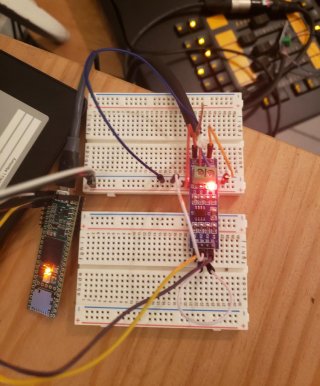
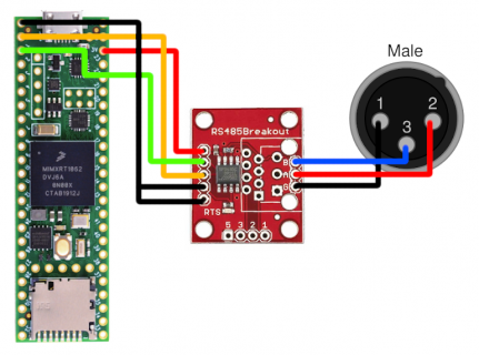
Here's a schematic and picture
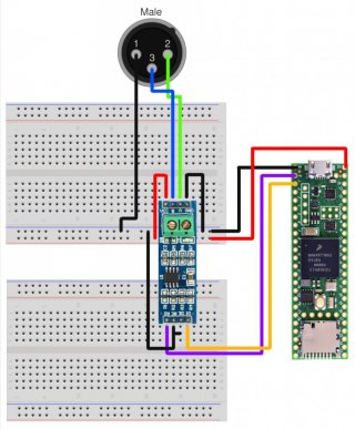
Scheme_Recieve.jpg Untitled.jpg

The A/B is connected to a 6 foot XLR cable I cut in half, could it be the fact that I'm not using proper DMX cable?

I've tried the following things with the same behavior:
  • Switching A/B on the RS-485 transceiver
  • Using the 3.3v rail
  • Disconnecting the TX
  • Sending LOW to DE and RE from a GPIO pin
  • Sending LOW to DE and RE using 2 separate GPIO pins
  • Connecting DE and RE to ground

I'm new to all this stuff and I'm not sure what else to try so any help or tips is greatly appreciated.

Thanks!
 
The RS485 module you are using is a 5V part. Meaning it will output a too high voltage on the RO line that could kill your Teensy 4.1 [Teensy 4.1 pins are 3V3 tolerant only].
You should look for a module that uses the MAX3485 part and will be powered by 3V3.

Not sure whether this solves your problem but this is a first observation.

Paul
 
Tried the Sparkfun DMX board on a Teensy 4.1 and it's working fine with the TeensyDMX library.
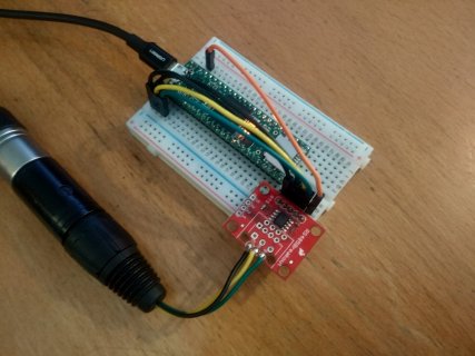
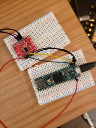
Here is the setup:

T4-DMXreceive.jpg
Pin 2 of the XLR plug connects to pin A on the SF board, XLR pin 3 to SF pin B, XLR pin 1 to SF pin G.

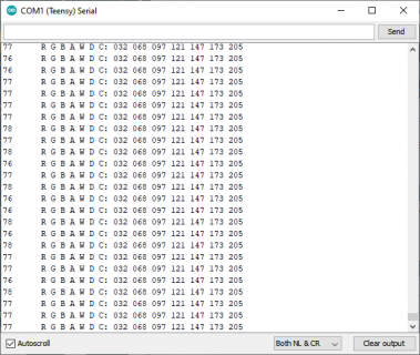
My DMX source sends out 7 channels. A DMX frame is sent every 76-78 msecs. The Teensy LED shows DMX activity.

The code I used:
Code:
#include <TeensyDMX.h>
namespace teensydmx = ::qindesign::teensydmx;

teensydmx::Receiver dmxRx{Serial1};
uint8_t buf[7] {0};
uint32_t previousMillis = 0;
uint32_t currentMillis = 0;

void setup() {
  pinMode(LED_BUILTIN, OUTPUT);
  Serial.println("Starting DMX receive");
  dmxRx.begin();
}

void loop() {
  currentMillis = millis();
  if (dmxRx.readPacket(buf, 1, 7) == 7) {
    digitalToggle(LED_BUILTIN);
    Serial.print(currentMillis - previousMillis); Serial.print("\t");
    previousMillis = currentMillis;
    Serial.printf("R G B A W D C: %03d %03d %03d %03d %03d %03d %03d\n", buf[0], buf[1], buf[2], buf[3], buf[4], buf[5], buf[6]);
  }
}
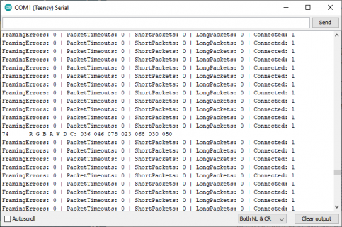
shows this on the serial monitor:

Serial.png

Paul
 
First off thank you so much for helping me with this.

I went out and got the correct transceiver this morning but I still can't seem to get it working.


Here's a schematic and image to make sure I'm following along correctly.
schemeatic2.pngsdfgsdfg.jpg

I added a little bit of code to print out the error stats
Code:
#include <TeensyDMX.h>
namespace teensydmx = ::qindesign::teensydmx;

teensydmx::Receiver dmxRx{Serial1};
uint8_t buf[7] {0};
uint32_t previousMillis = 0;
uint32_t currentMillis = 0;

void setup() {
  pinMode(LED_BUILTIN, OUTPUT);
  Serial.println("Starting DMX receive");
  dmxRx.begin();
}

void loop() {
  currentMillis = millis();
  if (dmxRx.readPacket(buf, 1, 7) == 7) {
    digitalToggle(LED_BUILTIN);
    Serial.print(currentMillis - previousMillis); Serial.print("\t");
    previousMillis = currentMillis;
    Serial.printf("R G B A W D C: %03d %03d %03d %03d %03d %03d %03d\n", buf[0], buf[1], buf[2], buf[3], buf[4], buf[5], buf[6]);
  } else {
    Serial.printf("FramingErrors: %d | PacketTimeouts: %d | ShortPackets: %d | LongPackets: %d | Connected: %d\n", 
      dmxRx.errorStats().framingErrorCount,
      dmxRx.errorStats().packetTimeoutCount,
      dmxRx.errorStats().shortPacketCount,
      dmxRx.errorStats().longPacketCount,
      dmxRx.connected()
     );
  }
}
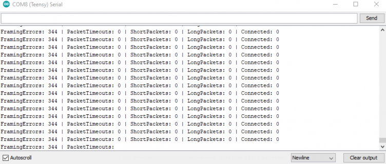
This is what it's outputting.
2.png

In the picture it looks like you have RX connected to the DI pin and the TX connected to the RO pin but it says "connect TX to the Driver Input and RX to the Receiver Output of the transceiver" under the hardware connection section in the libraries readme. I'm probably not understanding the transceiver circuit
Edit: I think I'm understanding the transceiver circuit better.

I've tried some other serial ports incase I fried Serial1 while I was using the 5v part. I also ran some basic sketches to make sure I didn't fry the teensy too.

Thanks again
 
and RX to the Receiver Output of the transceiver
Yeah, the Receiver Output of the transceiver is called "TX-O" on the Sparkfun board [it got me confused too initially...]. Anyway, you hooked it up correctly.

When I run your exact sketch, this is what is shown on the serial monitor:

Serial.png

Looks OK again.

Well, 2 things to check now:
1. Teensy Serial port 1 might be broken.
Try another serial port: connect the yellow wire to Teensy pin 7 [RX2] and the green wire to pin 8 [TX2] and change the constructor line to "teensydmx::Receiver dmxRx{Serial2};". You should see the correct data in the serial monitor. I just tried and it works.

2. DMX source/controller might be the source of the problem.
Can you verify one way or another that your DMX source is outputting valid data, either by connecting to a DMX spot or checking the DMX signal on an oscilloscope?

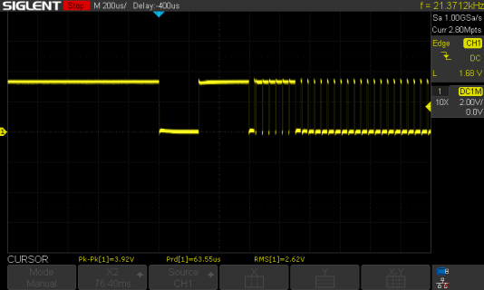
Here is what my scope shows on the TX-O output of the SF transceiver:

SDS00040.png

Paul
 
I have to comment that 3-pin XLR is disallowed by the DMX standard. But having said that, it looks like your non-inverting input (A) is connected to pin 2 and B is connected to pin 3. Try swapping those. After some searching, it appears that pin 2 should be connected to B and pin 3 should be connected to A. This also matches the 5-pin pinout, where B goes to pin 2 and A goes to pin 3.
 
I have to comment that 3-pin XLR is disallowed by the DMX standard
Correct. However, there are a lot of (semi)pro DMX spots out there with the 3-pin XLR. This is the spot I tested with.
You're right, I mixed up the pin numbers in message #4. Pin 2 of the XLR plug connects to pin B on the SF board, XLR pin 3 to SF pin A, XLR pin 1 to SF pin G.

Thanks,
Paul
 
Status
Not open for further replies.
Back
Top