
You are using an out of date browser. It may not display this or other websites correctly.
You should upgrade or use an alternative browser.
You should upgrade or use an alternative browser.
Teensy 4.1 pinout
- Thread starter Garug
- Start date
defragster
Senior Member+
Teensy 4.1 card backside has always been 'void of detail' since release 
Though it has recently been completed for production of new cards and a preview version posted by Paul somewhere.
Most of what it showed is on this page : https://www.pjrc.com/store/teensy41.html
It is clipped parts - as it will be on the back of the card because there is too much detail to fit with a whole image and arrows.
The cross row pins by the end of the SD adapter are the same as T_4.0 in order and function.
The USBHost pin placement and ordering is the same as T_3.6
The Ethernet pins shown on that page as are the surface mount pads for QSPI chip soldering PSRAM/FLASH
defragster
Senior Member+
This post :: TEENSY-4-1-where-do-I-connect-to-use-third-SPI
And that shows the pins routed to SDIO adapter too.
And that shows the pins routed to SDIO adapter too.
defragster
Senior Member+
Ok, Thanks. The links where useful, and I think I can get what is needed form them.
Great, if you need more detail on the thread are the Excel table versions provided by KurtE - and snapshot from his github repository
github.com/KurtE/TeensyDocuments
PaulStoffregen
Well-known member
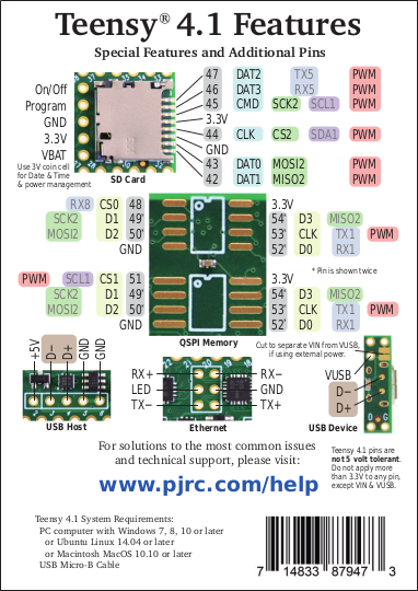
Finally, almost 9 months after we released Teensy 4.1, the pinout card has info on the back side!
I've updated the Teensy 4.1 product page and the pinout reference page.
https://www.pjrc.com/store/teensy41.html#pins
https://www.pjrc.com/teensy/pinout.html
Sorry this took so very long. We released Teensy 4.1 just a couple months after the pandemic hit. Robin & I have been struggling just to keep PJRC running and Teensy in stock, running short-staffed due to social distancing requirements. I am trying to get caught up on a huge backlog of stuff that's been set aside over the last several months. I'm happy to say the card design was updated recently and the new version is printed and will start shipping tomorrow.
Thanks Paul, I was sure when I made the question I had seen it and genuinely surprised when I could not find it.
"I'm happy to say the card design was updated recently" What issues did that address?
We have used the Teensy 3.2 and lately 4.0 a lot on our prototyping projects. Truly thank you for making such boards available and I am happy to find good support and friendly community at the forum too.
We are now looking in to use Teensy 4.1 on some Ethernet and USB Host projects.
PaulStoffregen
Well-known member
"I'm happy to say the card design was updated recently" What issues did that address?
Probably the main issue is access to the 3rd SPI port, which until now was documented only on Kurt's diagram and deep within the source code, and some threads on this forum.
Where to connect the coin cell for the RTC to keep date & time while power is off has also come up.
Usually this extra info isn't needed. Most people will only use the SD socket with a micro SD card, ethernet pins with the ethernet kit, the USB host port with the host cable, and the QSPI memory expansion with the PSRAM chip. You can certainly do any of those things without the back side of the card since the intended peripheral parts "just work" when used in the intended way. But still it kinda feels not so wonderful to be lacking documentation about the pinouts. If if this info isn't commonly needed, it's good to have it available.