Hello,
I am attempting to create a project, but I'm pretty much a novice.
The purpose of the project is to create a small form factor shield into which a teensy can be plugged and then used to control LED Lights.
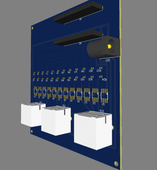
While with normal Arduino boards the shield sits on top with a Teensy the board needs to sit into the shield. Right now my first attempt looks like this

But because I need to run the power different routes I'm not able to place the teensy pins against the edge. Also I don't like the idea of it being so close to the edge. So I came up with a plan to mount a new USB jack on the edge of the board and then connect that to the Teensy.
However since I want the teensy to be removable I don't want to be soldering it to the board. In my ignorance I don't know how to go about creating a modular(?) connection for the D-, D+, Vcc and GND pads on the underside of the Teensy.
How does one go about connecting an external USB connection to the Teensy?
Extra detail for those who want to know what I'm up to
I'm using Easy EDA to design a PCB with the intention of having them print and mount all of the surface mount stuff since I don't think I can do that.
Then I will mount a DC jack and 3 RJ45 jacks. Ideally the Teensy will send it's 3.3V signal on each of the 12 pins and this will result in the 12V that is plugged into the board being turned on for remote lights connected via RJ45/Cat5e.
SO the board has 12 MOSFET switches some resistors that I guess are needed for the MOSFETs to work properly.
I hope to design a case that will expose the 3 RJ45 jacks, the USB Jack I'm asking about above, and the power jack, but otherwise be solidly enclosed thus protecting the Teensy board. It is expected to remain plugged into the computer as my purpose is to use it as a MIDI controlled light distributor. I've designed some remote boards which will take the RJ45 connection and break it out into the standards 2.1X5.5 barrel jacks I have for my LED lights.
The below link is what I get when I hit "Share" in Easy EDA and I've made it public so it should be visible.
https://easyeda.com/editor#id=|bb97d55e8eb845549517a8ae0046d747|4249db11c9f44a77883ffddf7457e06e|2f5c6bc133cb48c2809af2b4e8f8a3cb
I envision that it might also be useable with remote power supplies using the 12V signal over Cat5e as a relay signal instead of the actual power, but that would require a different remote board. Despite using RJ45 and cat5e it is not using ethernet it is just using a readily available form factor as a power cable.
I am attempting to create a project, but I'm pretty much a novice.
The purpose of the project is to create a small form factor shield into which a teensy can be plugged and then used to control LED Lights.
While with normal Arduino boards the shield sits on top with a Teensy the board needs to sit into the shield. Right now my first attempt looks like this

But because I need to run the power different routes I'm not able to place the teensy pins against the edge. Also I don't like the idea of it being so close to the edge. So I came up with a plan to mount a new USB jack on the edge of the board and then connect that to the Teensy.
However since I want the teensy to be removable I don't want to be soldering it to the board. In my ignorance I don't know how to go about creating a modular(?) connection for the D-, D+, Vcc and GND pads on the underside of the Teensy.
How does one go about connecting an external USB connection to the Teensy?
Extra detail for those who want to know what I'm up to
I'm using Easy EDA to design a PCB with the intention of having them print and mount all of the surface mount stuff since I don't think I can do that.
Then I will mount a DC jack and 3 RJ45 jacks. Ideally the Teensy will send it's 3.3V signal on each of the 12 pins and this will result in the 12V that is plugged into the board being turned on for remote lights connected via RJ45/Cat5e.
SO the board has 12 MOSFET switches some resistors that I guess are needed for the MOSFETs to work properly.
I hope to design a case that will expose the 3 RJ45 jacks, the USB Jack I'm asking about above, and the power jack, but otherwise be solidly enclosed thus protecting the Teensy board. It is expected to remain plugged into the computer as my purpose is to use it as a MIDI controlled light distributor. I've designed some remote boards which will take the RJ45 connection and break it out into the standards 2.1X5.5 barrel jacks I have for my LED lights.
The below link is what I get when I hit "Share" in Easy EDA and I've made it public so it should be visible.
https://easyeda.com/editor#id=|bb97d55e8eb845549517a8ae0046d747|4249db11c9f44a77883ffddf7457e06e|2f5c6bc133cb48c2809af2b4e8f8a3cb
I envision that it might also be useable with remote power supplies using the 12V signal over Cat5e as a relay signal instead of the actual power, but that would require a different remote board. Despite using RJ45 and cat5e it is not using ethernet it is just using a readily available form factor as a power cable.

