ARD-LTC1867 (16bit ADC) compatibility with teensy 3.6

Status
Not open for further replies.

khoadley

Member
Greetings,

I am hoping to use my teensy 3.6 to collect some data with 16bit resolution. While the ADS1115 works well, it is simply not fast enough. The ARD-LTC1867(iowa scaled engineering) is a shield made for the Arduino platform. It is a 16 bit ADC capable of taking up to 200,000 samples per second. This would be ideal, but I am having trouble getting it to work with the teensy. I know it is designed for the Uno or other arduino platforms, but I am hoping there might be a way to make it run on the teensy, but so far no luck. Does anyone know why this might not be working with the teensy 3.6? Alternatively, does anyone know of a 16 or 18 bit ADC with fast sampling rates (> 100,000 sps) that IS compatible with the teensy? Below is my code. Many thanks!

Kind Regards,

Kenneth D. Hoadley


Code:
#include <SPI.h>
#include <Wire.h>
#include "Ard1863.h"

const int Col0 = 1;

Ard186x ard186xboard1;
unsigned long sampleStartTimestamp;

void setup() 
{
  pinMode(Col0, OUTPUT);

  // initialize serial communications at 250000 bps:
  Serial.begin(250000);

  //  Wire.begin();
  SPI.begin();
  ard186xboard1.begin(DEVICE_LTC1867, ARD186X_EEP_ADDR_ZZ,3);
  //ard186xboard1.begin(DEVICE_LTC1867, ARD186X_EEP_DISABLE);

  ard186xboard1.ltc186xChangeChannel(LTC186X_CHAN_SINGLE_0P, 1);

  Serial.print("eeprom mac = [");
  Serial.print(ard186xboard1.eui48Get());
  Serial.print("]\n");

  Serial.print(" write 42 to eeprom[0] ");
  byte retval = ard186xboard1.eepromWrite(0, 42, true);
  Serial.print(" retval=");
  Serial.print(retval);
  Serial.print("\n");

  Serial.print("read eeprom[0] ");
  Serial.print(ard186xboard1.eepromRead(0, true));
  Serial.print("\n");

  sampleStartTimestamp = millis();  //save timestamp for the start of the sampling period
}

void loop() 
{
    // print the results to the serial monitor
    digitalWriteFast(Col0, HIGH);
    delayMicroseconds(10);
    Serial.println(ard186xboard1.ltc186xRead());
    digitalWriteFast(Col0, LOW);
    delay(1000);
}
 
I've used an LT1867 board from another project to successfully collect data on the T3.6. Here is the part of the code that interacts with the LT1867:

Code:
/**************************************************************
   This is the part of the DataLogger  test
   that handles data collection
   The Arduino IDE will merge this code with the main
   Sketch which is SOLO_Test_ADC.ino
   global variables must be defined in the main sketch
   9/27/2019
***************************************************************/

elapsedMicros adcelapsed;
IntervalTimer_VC CSTimer;
/******************************************************************
  // this function is called from the ADC interval timer
  // It does the ADC collection and storage in
  // input queue

   12/12/19  change buffers and types to simplify storing different
             number of channels: 2,4,8
********************************************************************/
#define CW(N)  (0x80+(N<<4)+0x04)
// i advals reassign words because sampling is 0 4 1 5 2 6 3 7
//const uint8_t chanwords[8] = {CW(1), CW(2), CW(3), CW(4), CW(5), CW(6), CW(7), CW(0)};
const uint8_t adchans[8] = {0, 2, 4, 6, 1, 3, 5, 7};
const uint8_t chanwords[8] = {CW(4), CW(1), CW(5), CW(2), CW(6), CW(3), CW(7), CW(0)};


static uint16_t adcState = 0;
uint32_t lastmicro;
//called on expiration of CStimer
// we always have to transfer numchans+1 values, otherwise the  last channel transferred
// would be in the next sample sequence.   That is why we do a dummy transfer at the
// start of the sampling interval just to set up the acquisition of the first channel (0)


void CSChore(void) {
  uint16_t result;
  uint8_t inbyte;
  uint16_t inword, cmdword;
  CSLO

  cmdword = (chanwords[adcState]) << 8;
  result = SPI.transfer16(cmdword);
  lastadc.adv[adcState] = result;

  adcState++;
  CSHI
  if (adcState >= (numchans)) {
    CSTimer.end();
    SPI.endTransaction();
    ADMARKLO
  }
}


// Called on expiration of ADCTimer
void ADCChore(void) {
  uint8_t dummy;
  // Channel 6 has random data 1V P-P
  // Channel 7 has microsecnds between ADC Chores

  lastadc.adv[7] = adcelapsed;
  adcelapsed = 0;
  lastadc.adv[6] = random(1000,27200);
  // when running at slow clock SPI baud rate will be divided by 6

  ADMARKHI
  adcState = 0;
  // before saving the result, IIR filters are applied
  if (GetDataState() == collecting)PutADCBuffer(&lastadc); 

  SPI.beginTransaction(SPISettings(24000000, MSBFIRST, SPI_MODE0));
  CSLO
  CSTimer.setClock(newclock);
  CSTimer.begin(CSChore, 10.0);

  dummy = SPI.transfer16((chanwords[7]) << 8); // selects channel 0
  //  dummy = SPI.transfer(chanwords[7]);  // selects channel 0
  //  dummy = SPI.transfer(0);  // selects channel 0
  CSHI
}

/********************************************************************
    Start the ADC collection intervaltimer
 ****************************************************************/
bool StartADC(uint32_t cRate) {
  // samplerate = cRate;
 // analog_init();

  delay(100);

  ADCTimer.setClock(newclock);
  ADCTimer.begin(ADCChore, 1000000 / cRate);
  ADCTimer.priority(30); // much higher than normal priority
  adcelapsed = 0;
  return true;
}

Hopefully there are some pertinent clues in the code. The tricky part of the LT1867 is sending the next channel identifier while reading the value from the LAST channel identifier. Properly used, the LT1867 is an excellent ADC and I've had good results with it for many years in many different projects. I'm getting to the end of a long day and I will look over your code in the morning.
 
Thanks for the reply mborgerson. I ended up switching to an Arduino Uno and it is now working (although the teensy would still be best). However, while it is still technically working, it seems to have a rather poor signal to noise ratio. In fact, the SN ratios is the same if it is at 12 bit or 16 bit. I had previously tried the adafruit ADS1115 (16 bit ADC) with the teensy and that gave a MUCH better SN ratio. However, the SPS speed was oto slow, which is why I am now trying the LTC1867. I am not sure if the adafruit_ads1115 is doing a lot of averaging in the background, but I was somewhat surprised by the low SN ratio from the LTC1867. Any chance there is something still wrong with my code?

I am also working on my light source to see if that might be the source of variability as well. Thanks in advance for your help!

Kind Regards,

Kenneth D. Hoadley
 
The LTC1867 only claims 89dB SNR, which is about 14.5 bits equivalent.
The ADS1115 claims full 16 bit noise-free at lower rates and not far off 16 bits at the full 860 SPS.

Couple this with the fact that noise amplitude goes with the square root of bandwidth, and you'll see why
the devices are very different - sampling at 200k SPS means 15 times the noise amplitude than sampling
at 860 SPS from the very same signal - assuming the quantization noise is not dominating and that suitable
antialiasing filtering is present. Without anti aliasing filters all bets are off for noise BTW, as the effective
noise bandwidth depends on the gating characteristics of the sample/hold circuitry. Most sigma-delta
ADCs tend to have a gating time comparable to the sample time though, so the noise bandwidth is comparable
to the sample rate.
 
Thanks MarkT! Sounds like I might need to rethink this a bit (unless anyone knows of a fast, high resolution ADC with better SNR than the LTC1867.

One of the issues I was having with the ADS1115 is that I cant actually get it to sample at a full 860 SPS. Looking at the GitHub page for the ADS1115, it seems like this is an issue others are having as well. Any chance anyone here might have a workaround? I have pasted my current code below. Many thanks for your help!!

Kind Regards,

Kenneth D. Hoadley

Code:
#include <SD.h>
#include <SPI.h>
#include <string.h>
#include <Wire.h>
#include <Adafruit_ADS1015.h>

const int chipSelect = BUILTIN_SDCARD;
const int SIG = A0;   //Analog channel used for reading fluorescence signal
int STARTER;
File myFile;
String PSIFile = "DatPSI.csv";
float COL0Sig; // variable to store the value coming from Fluoresence Channel
const int input1 = 14;
const int Col0 = 1; //digitalWrite pin for UV LED excitation -blue-label-in-code-
int W;
int otp=0;
Adafruit_ADS1115 ads;

void setup() 
{    Serial.begin(9600);
     Serial4.begin(38400);
     pinMode(Col0, OUTPUT);
     pinMode(input1, INPUT);
     pinMode(SIG, INPUT);
     ads.begin();
     //ads.setSampleRate(ADS1115_DR_860SPS);    Does not work
}

void loop() 
{   
   STARTER = digitalRead(input1);
   if(STARTER==LOW && otp ==0)
   {  
      requestEvent();
      delay(50);
      otp=0;
   }
   if (STARTER == HIGH && otp==0)
   {
        if (SD.exists(PSIFile.c_str()))
        {   myFile = SD.open(PSIFile.c_str(), FILE_WRITE);
            myFile.print("PSI");
        }
        else 
        {   
            File myFile = SD.open(PSIFile.c_str(), FILE_WRITE);
            myFile.print("PSI");
        }
        otp=1;
   }
   if (STARTER == HIGH && otp==1)
   {          
    
              int16_t adc0;
              digitalWriteFast(Col0, HIGH);
              delayMicroseconds(10);
              adc0 = ads.readADC_SingleEnded(0);
              digitalWriteFast(Col0, LOW);
              Serial.println(adc0);
              myFile.print(',');
              myFile.print(adc0);
              delay(1000);   
              otp=1;
   } 
   if(STARTER==LOW && otp ==1)
   { 
        myFile.println();
        myFile.close();
        otp=0;
   }
}

void requestEvent()
{     
      while (Serial4.available()>0)
      {
         String dats = Serial4.readStringUntil('>');
         char first = dats.indexOf('>');
         PSIFile = dats.substring(0,first);
      }
}

void sdSave()
{
     //Initialize the SD card
     //Serial.println("Initializing SD card...");
     if (!SD.begin(chipSelect)) 
     {    //Serial.println("initialization failed!");
     }
     else
     {    //Serial.println("initialization done.");
     }
     delay(1000);
}
 
MarkT;271611 Most sigma-delta ADCs tend to have a gating time comparable to the sample time though said:
The LT1867 is a capacitive Successive Approximation ADC. The input acquisition time is a nominal 1.1 microseconds, independent of the sample rate.

As noted, it is imperative to have good anti-aliasing filters at the input if you have high-bandwidth or noisy sensors. In an application dating back to 2010, I used a 2-pole Sallen-Key lowpass filter with a cutoff of -3dB at 40Hz and -35dB at 400Hz. I sampled at 400Hz and used a 30-pole FIR filter with a notch of -100dB at 60Hz to get rid of ambient 60Hz noise. The results were stored at 100 samples per second. The system is still used in a sensor to measure ocean turbulence where the signals of interest are in the 5 to 35Hz range. With the inherent oversampling of the FIR filter, the noise level was about +/- 1 LSB.

In my application, I used the LT1867L, which runs off 3.3 V and has an input range of 0 to 2.5V. The ARD board uses the LT1867, which is a 5V devices--although the board does have onboard level shifters to make is 3.3V compatible. If you are going to use this board, don't depend on the Teensy 5V USB output for power--way too much droop and noise.

I can't comment on the problems in the OP's code as it hides all the important stuff in the ARD library, which I haven't yet downloaded.

With proper input filters and some low-pass digital filtering, you should be able to sample multiple channels at 8000 samples per second, run them through an FIR or IIR digital filter and store the results at 1 to 2KHz.

I'll see if I can dig up some data files from my testing of the LT1867L with the T3.6.
 
My point was that the ADS1115 is inherently integrating over its long sample period, so will have relatively little issue
with wideband noise at the input.

If you want a fast >=16 bit ADC, the ADS8885 is 18 bit SAR with 400kSPS max rate and 100dB SNR. It's got
half the power consumption of the LTC1867 at twice the sample rate too. Don't know if anyone sells a module
for it though.
 
@khoadley, if you look at the schematic - for Teensy - it seems you need to provide 3.3V to "VIO" (do NOT close JP7), and in addition the board wants 5V.
 
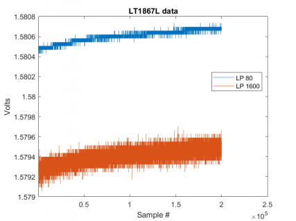
I dug out my LT1867L board and recorded a data file with all 8 channels connected to a 1.5V alkaline battery and sampled at 4000 samples/second. Data from each of the first four channels passed through an 8-pole IIR Butterworth low-pass filter implemented on the T3.6. The filtered data was rounded and stored as uint16_t values on the SD card. Here is a plot of a portion of the data: LP80 is the channel with the 80Hz low pass filter. LP1600 has the 1600Hz lowpass filter.
LT1867.png

As you can see, oversampling and filtering works well. The T3.6 has the horse power to do the filtering while sampling and that allows you to use the data for control as well as just storing it for later analysis (as I did in Matlab to generate the plot).

The OP didn't specify exactly what sample rate and number of channels was needed. However, I think the T3.6 could probably handle 4 channels sampled at 10KHz. Filtering and decimation to store 4 channels at 1KHz should be possible. That's really more like low to medium speed compared to the 1Megasample collection that has been demonstrated on the T4.1.
 
Status
Not open for further replies.
Back
Top