I've read the many other (Teensy) threads about Logic Level Conversion (and looked at many of the products referenced). I need bi-directional Logic Level Conversion from/to the Teensy 4.0 SPI ports; I am driving the SPI MOSI port both directions (data rate is ~20 MHz), interfacing with an external 5V device.
I have "successfully" used the TXS0108E (https://www.ti.com/lit/ds/symlink/txs0108e.pdf); the word "successfully" is in quotes since one completed system works flawlessly, and the other one is "glitchy". I am trying to understand the underlying issue and believe it to be related to TXS0108E. The datasheet indicates:
• Maximum data rates
– 110 Mbps (push pull)
– 1.2 Mbps (open drain)
There are some things I am trying to figure out:
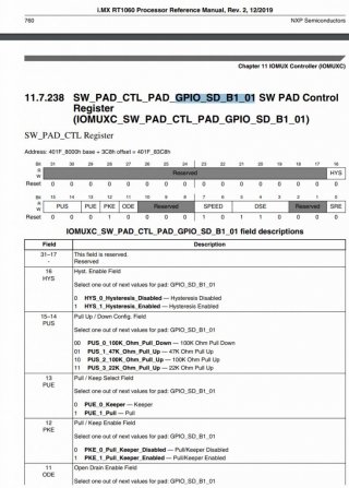
(1) How do I determine whether my SPI MOSI pins are "push pull" or "open drain"? I'd like to assume they are, by default, "push pull" in order to support SPI high data rates, but I don't know.
(2) To keep my wiring simple, I've tied the OE of the TXS0108E to 3.3V using a 1k ohm resistor. This "violates" the suggestion from the datasheet "To ensure the Hi-Z state during power-up or powerdown periods, tie OE to GND through a pull-down resistor." Is this something I should worry about?
(3) Regarding #2 above, should I be using one of the Teensy's digital I/O pins to enable the chip somewhere in my setup? Do the Teesny's pins default to GND during the poweron sequence?
(4) Are there reasons I should not use this chip? The features on the cover sheet make it seem like the ideal logic level converter; I just wish there was a smaller 4-channel offering since I don't need all 8 channels.
(5) I am making the SPI MOSI pin the master some of the time, acting as the slave some of the time, and inactive the reset of the time. How do these chips, like the TXS0108E, know which side is trying to drive the line and decide when to drive the other side? The answer may indicate what should I be doing with the SPI MOSI line to help this dynamic switching.
Thanks, Jim
I have "successfully" used the TXS0108E (https://www.ti.com/lit/ds/symlink/txs0108e.pdf); the word "successfully" is in quotes since one completed system works flawlessly, and the other one is "glitchy". I am trying to understand the underlying issue and believe it to be related to TXS0108E. The datasheet indicates:
• Maximum data rates
– 110 Mbps (push pull)
– 1.2 Mbps (open drain)
There are some things I am trying to figure out:
(1) How do I determine whether my SPI MOSI pins are "push pull" or "open drain"? I'd like to assume they are, by default, "push pull" in order to support SPI high data rates, but I don't know.
(2) To keep my wiring simple, I've tied the OE of the TXS0108E to 3.3V using a 1k ohm resistor. This "violates" the suggestion from the datasheet "To ensure the Hi-Z state during power-up or powerdown periods, tie OE to GND through a pull-down resistor." Is this something I should worry about?
(3) Regarding #2 above, should I be using one of the Teensy's digital I/O pins to enable the chip somewhere in my setup? Do the Teesny's pins default to GND during the poweron sequence?
(4) Are there reasons I should not use this chip? The features on the cover sheet make it seem like the ideal logic level converter; I just wish there was a smaller 4-channel offering since I don't need all 8 channels.
(5) I am making the SPI MOSI pin the master some of the time, acting as the slave some of the time, and inactive the reset of the time. How do these chips, like the TXS0108E, know which side is trying to drive the line and decide when to drive the other side? The answer may indicate what should I be doing with the SPI MOSI line to help this dynamic switching.
Thanks, Jim