inmbolmie
New member
Hi, if you want to fast-forward the story, the direct questions are at the end marked bold.
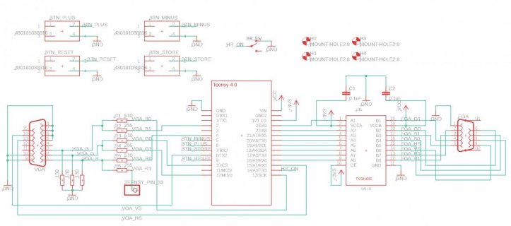
I have an issue with a report of a bricked Teensy 4.0 used with my EGA/CGA to VGA board described here.
The event was like this: The Teensy was working but after some cycles of programming/plugging/unplugging from a Tandy 1000EX went bricked (no life, no usb, 15 second restore doesn't do anything).
Me personally have treated my Teensies very roughly during development, even adding to this kind of operation some over voltages, overheating, reverse polarities, etc, for months, never having an issue. So it comes to my mind some kind of ESD event with the user setup as a possibility.
The complete schematics are here https://github.com/inmbolmie/T4_EGA_VGA#schematics. The computer side from the EGA port perspective is essentially a 74LS244 (it has very low current sourcing capabilities) driving the 8 CGA/EGA signals up to the TXS0108 inputs, plus a grounding shield that is NOT connected at the Teensy side. The VGA signals are only output so I think they can be ignored. The Teensy is powered from the USB connector.

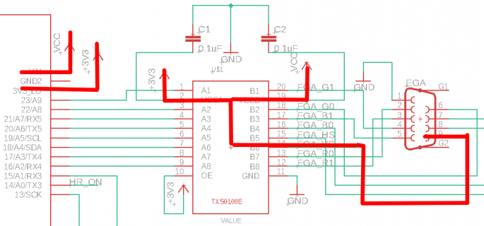
My theory is like this: I simply ignored any ESD issue coming from the EGA connector because I have the TXS0108 in between, and it has in-built ESD protection. But what I didn't consider is that the 3,3V and 5V pins (VCCA, VCCB) to power the TXS, that are directly connected to the Teensy, can leak voltage back supposedly from the input pins protection diodes of the TXS inputs. In fact, now measuring the pins with the board unpowered and the EGA port plugged in, like 2-3 volts are coming back to the Teensy mainly from the VSYNC/HSYNC signals. So *maybe* ESD-protecting the input pins only had the effect of diverting the voltage peaks back to the Teensy via 3,3V and 5V pins through the protection diodes... The theory is, that fiddling with the EGA connector some sparks could have jumped from the computer grounding case to one of the pins (because inadequate grounding, ambient conditions etc), passed from the input pin to the 3,3V rail via ESD protection and proceed to fry the Teensy 4.0 internals.

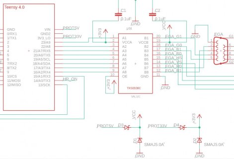
I've been thinking about adding a layer of protection to the power pins like this, with a shottky to block reverse currents and a TVS device to divert voltage peaks out of the Teensy:

The questions are:
Does all of this weirdness of a voltage peak passing through a TXS0108 make any sense to you?
Would be enough to protect like described the 3,3V and 5V Teensy pins?
Is there any recommendation for adequate partnumbers for the TVS diodes or whatever parts you consider necessary?
I would be very thankful if anyone is willing to share its experiences here.
I also have read posts suggesting using 74LCX devices for high impedance while the circuit is powered-off, but I don't know if that would also apply to this problem of reverse voltages coming to Vcc from protection diodes.
Thanks and best regards.
I have an issue with a report of a bricked Teensy 4.0 used with my EGA/CGA to VGA board described here.
The event was like this: The Teensy was working but after some cycles of programming/plugging/unplugging from a Tandy 1000EX went bricked (no life, no usb, 15 second restore doesn't do anything).
Me personally have treated my Teensies very roughly during development, even adding to this kind of operation some over voltages, overheating, reverse polarities, etc, for months, never having an issue. So it comes to my mind some kind of ESD event with the user setup as a possibility.
The complete schematics are here https://github.com/inmbolmie/T4_EGA_VGA#schematics. The computer side from the EGA port perspective is essentially a 74LS244 (it has very low current sourcing capabilities) driving the 8 CGA/EGA signals up to the TXS0108 inputs, plus a grounding shield that is NOT connected at the Teensy side. The VGA signals are only output so I think they can be ignored. The Teensy is powered from the USB connector.

My theory is like this: I simply ignored any ESD issue coming from the EGA connector because I have the TXS0108 in between, and it has in-built ESD protection. But what I didn't consider is that the 3,3V and 5V pins (VCCA, VCCB) to power the TXS, that are directly connected to the Teensy, can leak voltage back supposedly from the input pins protection diodes of the TXS inputs. In fact, now measuring the pins with the board unpowered and the EGA port plugged in, like 2-3 volts are coming back to the Teensy mainly from the VSYNC/HSYNC signals. So *maybe* ESD-protecting the input pins only had the effect of diverting the voltage peaks back to the Teensy via 3,3V and 5V pins through the protection diodes... The theory is, that fiddling with the EGA connector some sparks could have jumped from the computer grounding case to one of the pins (because inadequate grounding, ambient conditions etc), passed from the input pin to the 3,3V rail via ESD protection and proceed to fry the Teensy 4.0 internals.

I've been thinking about adding a layer of protection to the power pins like this, with a shottky to block reverse currents and a TVS device to divert voltage peaks out of the Teensy:

The questions are:
Does all of this weirdness of a voltage peak passing through a TXS0108 make any sense to you?
Would be enough to protect like described the 3,3V and 5V Teensy pins?
Is there any recommendation for adequate partnumbers for the TVS diodes or whatever parts you consider necessary?
I would be very thankful if anyone is willing to share its experiences here.
I also have read posts suggesting using 74LCX devices for high impedance while the circuit is powered-off, but I don't know if that would also apply to this problem of reverse voltages coming to Vcc from protection diodes.
Thanks and best regards.

