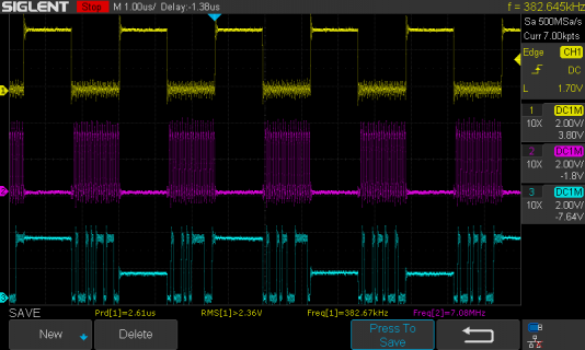
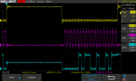
I'm got some proof-of-concept code to interface to these ADCs, which are SAR 18 bit 400kSPS (ie
_not_ sigma-delta so have very low latency, and a 1.2µs settling time to 18 bits) They are not I2S,
note.
datasheet: https://www.ti.com/lit/ds/sbas568a/sbas568a.pdf
I already had a test board for these I'd been using on another microcontroller for playing around with
spectrum analysis (cut down dynamic signal analyzer, basically).
To get them working at the highest speed for audio sampling (384kSPS), the timing is tight as there is
a 1.3µs conversion time before 18 bits can be clocked out at a maximum of 16MHz, all having to fit
in about 2.5µs.
And of course for spectral analysis the aperture jitter is crucial at 18 bit resolution, so its vital to trigger
the start-conversion pin precisely regularly.
I thus have figured out how to use FLEXPWM to drive the start-conversion pin and trigger an interrupt
from which the bits can be clocked out.
Thought I'd share the method I've used, which involved figuring out how FLEXPWM is driven in pwm.c
in the runtime, and how to get PWM compare interrupts:


Not being sigma-delta these ADCs can be calibrated accurately to a voltage reference, which allows
precision measurements to be made in a way most audio conversion chips cannot. I think the spec on
the chip is +/-0.01% accuracy given a good reference. The thermal gain drift is 0.15ppm/C, and THD
- 115dB (despite being SAR technology, its no-missing-codes and ultra low distortion)
_not_ sigma-delta so have very low latency, and a 1.2µs settling time to 18 bits) They are not I2S,
note.
datasheet: https://www.ti.com/lit/ds/sbas568a/sbas568a.pdf
I already had a test board for these I'd been using on another microcontroller for playing around with
spectrum analysis (cut down dynamic signal analyzer, basically).
To get them working at the highest speed for audio sampling (384kSPS), the timing is tight as there is
a 1.3µs conversion time before 18 bits can be clocked out at a maximum of 16MHz, all having to fit
in about 2.5µs.
And of course for spectral analysis the aperture jitter is crucial at 18 bit resolution, so its vital to trigger
the start-conversion pin precisely regularly.
I thus have figured out how to use FLEXPWM to drive the start-conversion pin and trigger an interrupt
from which the bits can be clocked out.
Thought I'd share the method I've used, which involved figuring out how FLEXPWM is driven in pwm.c
in the runtime, and how to get PWM compare interrupts:
Code:
#include <Audio.h>  // seem to need this to get at imxrt_hw.h, build logic perhaps?
#include "utility/imxrt_hw.h"


/*
 * PWM driven regular sampling via a pair of ADS8885 SAR 18-bit ADCs.  PWM hardware
 * ensures the aperture timinng is consistent (the chip has jitter of only 5ps, which is good
 * to 19 bits resolution if driven from low-jitter CONVST clock)
 *
 * The PWM compare interrupt is used to then drive the serial transfer once the 1.3us acquisition
 * time is complete - this should be done with SPI hardware really.
 *
 * This sort of ADC has enough resolution for audio, is fast enough for 384kSPS, and has an
 * 18-bit settling time of 1.2us, so could be useful for ultra-low latency processing if coupled
 * with a non-sigma-delta DAC
 *
 * TODO:
 * * feed samples into a circular buffer
 * * turn into an audio library input class
 */

#if !defined(__IMXRT1062__)
#error Needs Teensy4
#endif

// ADS8885 pins
#define ADS8885_DIN        2
#define ADS8885_SCLK       3
#define ADS8885_CONVST     4
#define ADS8885_DOUTleft   5  // two ADS8885's on the test pcb, so two outputs.
#define ADS8885_DOUTright  6


#define ADS8885_ACQ_TIME_US  1.3            // from datasheet, max acquisition time
#define FREQ                 (8 * 48000.0)  // 384kSPS, close to the 400kSPS max for ADS8885


// FLEXPWM setup for pin 4, gleaned from the file pwm.c in the Teensy4 runtime,
// unit FLEXPWM2, submodule 0, channel 1 (which is VAL3 counter)
#define PWM_unit     IMXRT_FLEXPWM2
#define PWM_irq      IRQ_FLEXPWM2_0
#define PWM_submodule 0
#define PWM_counter  VAL3   // channel 1
#define PWM_cntbit   3      //
#define PWM_status   FLEXPWM2_SM0STS
#define PWM_int_en   FLEXPWM2_SM0INTEN


void read_ADC (void)  // single conversion, for standalone use (not used here)
{
  digitalWriteFast (ADS8885_CONVST, HIGH) ;
  delayNanoseconds (1300) ;
  digitalWriteFast (ADS8885_CONVST, LOW) ;
  delayNanoseconds (20) ;
  inner_read_ADC () ;
}


volatile int32_t datawordL = 0, datawordR = 0  ;   // results from conversion stored here

inline void inner_read_ADC (void)   // does the SPI-like part of transaction, currently bit-banged
{
  int count = 18 ;
  int32_t dataL, dataR ;
  do
  {
    digitalWriteFast (ADS8885_SCLK, HIGH) ;
    int nextbitL = digitalReadFast (ADS8885_DOUTleft) ;
    int nextbitR = digitalReadFast (ADS8885_DOUTright) ;
    //delayNanoseconds (6) ;
    digitalWriteFast (ADS8885_SCLK, LOW) ;
    delayNanoseconds (16) ;
    dataL = (dataL << 1) | nextbitL ;
    dataR = (dataR << 1) | nextbitR ;
  } while (--count > 0) ;
  datawordL = dataL << 14 >> 14 ;  // produced signed output
  datawordR = dataR << 14 >> 14 ;
}


// The ISR - at this point the PWM'd CONVST pulse has just ended.
void pwm_irq (void)
{
  PWM_status = 1<<PWM_cntbit ;  // clear interrupt flag
  inner_read_ADC() ;
}

uint32_t time_to_PWM_counter (float microsecs)
{
  return (uint32_t) (F_BUS_ACTUAL * microsecs / 1e6);
}

uint32_t freq_to_PWM_counter (float Hz)
{
  return (uint32_t) ((float)F_BUS_ACTUAL / Hz + 0.5f);
}


void setup()
{
  Serial.begin (115200) ;

  // setup pins for ADS8885
  pinMode (ADS8885_DIN, OUTPUT) ;
  pinMode (ADS8885_SCLK, OUTPUT) ;
  pinMode (ADS8885_CONVST, OUTPUT) ;
  pinMode (ADS8885_DOUTleft, INPUT) ;
  pinMode (ADS8885_DOUTright, INPUT) ;
  digitalWrite (ADS8885_DIN, HIGH) ;

  // setup PWM
  // Use analogWrite machinery to setup the basic pin4 PWM, which will be partly be redefined
  analogWriteFrequency (ADS8885_CONVST, FREQ) ;
  analogWrite (ADS8885_CONVST, 31) ;

  uint32_t period = freq_to_PWM_counter (FREQ);
  int prescale = 0 ;
  while (period > 0xFFFF && prescale < 7)
  {
    period >>= 1;
    prescale += 1;
  }

  PWM_unit.MCTRL                 |= FLEXPWM_MCTRL_CLDOK (1<<PWM_submodule);
  PWM_unit.SM[PWM_submodule].CTRL = FLEXPWM_SMCTRL_FULL | FLEXPWM_SMCTRL_PRSC (prescale);
  PWM_unit.SM[PWM_submodule].VAL1 = period ;  // PWM frequency
  PWM_unit.SM[PWM_submodule].PWM_counter = time_to_PWM_counter (ADS8885_ACQ_TIME_US) ;
  PWM_unit.OUTEN                 |= FLEXPWM_OUTEN_PWMA_EN (1<<PWM_submodule);
  PWM_unit.MCTRL                 |= FLEXPWM_MCTRL_LDOK (1<<PWM_submodule);

  // finally fire up PWM compare interrupt on pin 4 (CONVST pin).
  attachInterruptVector (PWM_irq, pwm_irq) ;
  NVIC_SET_PRIORITY (PWM_irq, 127);   // higher prio than standard as timing critical
  NVIC_ENABLE_IRQ (PWM_irq);
  PWM_int_en |= 1<<PWM_cntbit ;

}

void loop()
{
  noInterrupts () ;
  int left = datawordL ;
  interrupts () ;
  Serial.println (left) ;
  delay(200) ;
}

Not being sigma-delta these ADCs can be calibrated accurately to a voltage reference, which allows
precision measurements to be made in a way most audio conversion chips cannot. I think the spec on
the chip is +/-0.01% accuracy given a good reference. The thermal gain drift is 0.15ppm/C, and THD
- 115dB (despite being SAR technology, its no-missing-codes and ultra low distortion)

