Hiya,
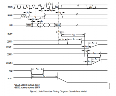
Im having problems getting my AD5390 DAC to get to work. Right now I just want to send it a simple sequence to see if it is working, but it is not. Here is the datasheet for the SPI output order:

one thing i dont understand is the BUSY, LDAC, and the second clock pulse with '24' at the top.
... what do those // mean before it? im assuming its like 'just continue' which in that case would mean just do nothing.
how do you send a single clock pulse??
also i fudged the BUSY and LDAC below.. but how are you supposed to do that?
and here is how the data bytes are supposed to formated:

and here is a scope screen caps: (i dont have access to a logic analyzer...)
channel 1 : SCK
channel 2 : DATA
channel 3: SYNC
channel 4: Output 1 of the dac
this one is just those 3,

this is me trying to implement the busy, ldac, and then another clock signal to (kinda) match the datasheet:
channel 1-3 : same as above,
channel 4: busy
channel 5: LDAC
channel 6: DAC output

and here is the code:
THANK YOU for any insight !! I am obviously very new to this, but do have good experience and background with electronics and programming.
Im having problems getting my AD5390 DAC to get to work. Right now I just want to send it a simple sequence to see if it is working, but it is not. Here is the datasheet for the SPI output order:
one thing i dont understand is the BUSY, LDAC, and the second clock pulse with '24' at the top.
... what do those // mean before it? im assuming its like 'just continue' which in that case would mean just do nothing.
how do you send a single clock pulse??
also i fudged the BUSY and LDAC below.. but how are you supposed to do that?
and here is how the data bytes are supposed to formated:
and here is a scope screen caps: (i dont have access to a logic analyzer...)
channel 1 : SCK
channel 2 : DATA
channel 3: SYNC
channel 4: Output 1 of the dac
this one is just those 3,
this is me trying to implement the busy, ldac, and then another clock signal to (kinda) match the datasheet:
channel 1-3 : same as above,
channel 4: busy
channel 5: LDAC
channel 6: DAC output
and here is the code:
Code:
#include <SPI.h>

const int slaveSelectPin = 10;
byte header = 0b01000000; // first two 4 bits are 0100 -- disable toggle mode, enable write , then two blank
byte address;   // this is just 4 bits but we will OR it with header
word regi = 0b1100000000000000; // need the first 2 bits of the data word to be 11 to select the input data register
word value; // this will be a 14 bit number, go up to 16384.
byte valueHighByte;
byte valueLowByte;
const int busyPin = 2;
const int ldac = 3;


void setup() {
  // set the slaveSelectPin as an output:
  pinMode (slaveSelectPin, OUTPUT);
  pinMode (busyPin, OUTPUT);
  pinMode (ldac, OUTPUT);
  digitalWrite (slaveSelectPin, HIGH);
  // initialize SPI:
  SPI.begin();
}

void loop() {
  address = 0;
  for (value = 0; value < 16383; value++) {
    Serial.print("value going up is :");
    Serial.println(value, BIN);
    dacWrite(address, value);
    delay(1);
  }
  delay(100);
  for (value = 16383; value > 0; value--) {
    Serial.print("value going down is :");
    Serial.println(value, BIN);
    dacWrite(address, value);
    delay(1);
  }
}

void dacWrite(byte address, word value) {
  // gain control of the SPI port
  // and configure settings
  SPI.beginTransaction(SPISettings(4000000, MSBFIRST, SPI_MODE0));
  // take the SS pin low to select the chip:
  //  send in the address and value via SPI:
  byte beginning = (header | address);
  word data = (regi | value);
  beginning = beginning >> 0;
  valueHighByte = highByte(data);
  valueLowByte = lowByte(data);
    Serial.print("header byte is: ");
    Serial.println(beginning, BIN);
    Serial.print("data word is: ");
    Serial.println(data, BIN);
  digitalWrite(slaveSelectPin, LOW);
  SPI.transfer(beginning);
  SPI.transfer(valueHighByte);
  SPI.transfer(valueLowByte);
  // take the SS pin high to de-select the chip:
  digitalWrite(slaveSelectPin, HIGH);
  digitalWrite(busyPin, LOW);
  digitalWrite(ldac, LOW);
  delayMicroseconds(1); // just wait a second to match the data sheet
  digitalWrite(ldac, HIGH); // ldac goes high first just like the datasheet
  delayMicroseconds(1);
  digitalWrite(busyPin, HIGH); // then busy pin goes high
  SPI.transfer(HIGH); // idk... to get a clock signal for it to go??
  // release control of the SPI port
  SPI.endTransaction();
}
THANK YOU for any insight !! I am obviously very new to this, but do have good experience and background with electronics and programming.