MicroMod Beta Testing

8MB Flash and PJRC bootloader not listed on "FEATURES"
Code:
3x Serial Ports (one dedicated to USB, two Serial UART)
2x SPI
2x I2C Bus
1x CAN-Bus
1x I2S Digital Audio
USB Host
1x SDIO for SD
2x Dedicated Analog Pins (Up to 14 available for use)
2x Dedicated PWM Pins (Up to 22 available for use)

Only $1 more than SAMD51
 
I also ordered a couple of the released boards :D

They could really learn from PJRC's pinout cards. Even after looking at the SparkFun Hookup Guide table, it's not easy planning how I would use all the pins.

For what it is worth, during the beta of the board, I added pages to my T4.x Excel document about the different pins... https://github.com/KurtE/TeensyDocuments/blob/master/Teensy4 Pins.xlsx

There are probably a few minor updates I need to do as we have changed a few minor things, like a couple of objects have changed recently...
Not the Actual pins. .. That is:
Code:
Pin	MM Pin	Name	GPIO	Serial	I2C	SPI	PWM	CAN	Audio	XBAR	FlexIO	Analog	SD/CSI/LCD
 0	17	AD_B0_03	1.3	Serial1(6) RX		SPI1(3) CS0	PWM1_X1	2_RX		IO-17			
 1	19	AD_B0_02	1.2	Serial1(6) TX		SPI1(3) MISO	PWM1_X0	2_TX		IO-16			
 2	47	EMC_04	4.4				PWM4_A2		2:TX_DATA	IO-06	1:4		
 3	32	EMC_05	4.5				PWM4_B2		2:TX_SYNC	IO-07	1:5		
 4	10	EMC_06	4.6				PWM2_A0		2:TX_BCLK	IO-08	1:6		
5	18	EMC_08	4.8				PWM2_A1		2:RX_DATA	IO-17	1:8		
6	71	B0_10	2.10				PWM2_A2, QT4_1		1:TX3_RX1		2:10		LCD_DATA6
7	56	B1_01	2.17	Serial2(4) RX			PWM1_B3		1:TX_DATA	IO-15	2:17, 3:17		
8	54	B1_00	2.16	Serial2(4) TX			PWM1_A3		1:RX_DATA	IO-14	2:16, 3:16		
 9	69	B0_11	2.11				PWM2_B2,QT4_2		1:TX2_RX2		2:11		LCD_DATA7
10	55	B0_00	2.0			SPI(4) CS0	QT1_0		MQS_RIGHT		2:0     		LCD_CLK
11	59	B0_02	2.2			SPI(4) MOSI	QT1_2	1_TX			2:2		LCD_HSYNC
12	61	B0_01	2.1			SPI(4) MISO	QT1_1		MQS_LEFT		2:1     		LCD_ENABLE
13	57	B0_03	2.3			SPI(4) SCK	QT2_0	1_RX			2:3		LCD_VSYNC
14/A0	34	AD_B1_02	1.18	Serial3(2) TX			QT3_2		SPDIF_OUT		3:2	A1:7, A2:7	
15/A1	38	AD_B1_03	1.19	Serial3(2) RX			QT3_3		SPDIF_IN		3:3	A1:8, A2:8	
16/A2	20	AD_B1_07	1.23	Serial4(3) RX	Wire1(3) SCL				SPDIF_EXTCLK		3:7	A1:12, A2:12	USDHC2_DATA3
17/A3	22	AD_B1_06	1.22	Serial4(3) TX	Wire1(3) SDA				SPDIF_LOCK		3:6	A1:11, A2:11	USDHC2_DATA2
18/A4	12	AD_B1_01	1.17	Serial3(2) RTS	Wire(1) SDA		QT3_1				3:1	A1:6, A2:6	
19/A5	14	AD_B1_00	1.16	Serial3(2) CTS	Wire(1) SCL		QT3_0				3:0	A1:5, A2:5	
20/A6	52	AD_B1_10	1.26	Serial5(8) TX					1:RX_SYNC		3:10	A1:15, A2:15	
21/A7	50	AD_B1_11	1.27	Serial5(8) RX					1:RX_BCLK		3:11	A1:0, A2:0	
22/A8	49	AD_B1_08	1.24				PWM4_A0	1_TX			3:8	A1:13, A2:13	USDHC2_CMD
23/A9	58	AD_B1_09	1.25				PWM4_A1	1_RX	1:MCLK		3:9	A1:14, A2:14	USDHC2_CLK
---		----	----	------	---	---	---	---	----	----	-----	------	
24/A10	53	AD_B0_12	1.12	Serial6(1) TX	Wire2(4) SCL		PWM1_X2					A1:1  	
25/A11	51	AD_B0_13	1.13	Serial6(1) RX	Wire2(4) SDA		PWM1_X3	GPT1_CLK				A1:2	
26/A12	67	AD_B1_14	1.30			SPI1(3) MOSI			1:TX_BCLK		3:14	A2:3  	
27/A13	8	AD_B1_15	1.31			SPI1(3) SCK			1:TX_SYNC		3:15	A2:4  	
28	4	EMC_32	3.18	Serial7(7) RX			PWM3_B1						
29	16	EMC_31	4.31	Serial7(7) TX		SPI2(1) CS1	PWM3_A1						
30	41	EMC_37	3.23				GPT1_3 	3_RX	3:MCLK	IO-23			
31	43	EMC_36	3.22				GPT1_2	3_TX	3:TX_DATA	IO-22			
32	65	B0_12	2.12						1:TX1_RX3	IO-10	2:12		LCD_DATA8
33	63	EMC_07	4.7				PWM2_B0		2:MCLK	IO-09	1:7		
SD Pins - Cable connector(T4 34-39)													
34	66	SD_B0_03	3.15	Serial5(8) RTS		SPI2(1) MISO	PWM1_B1			IO-07			DATA1
35	64	SD_B0_02	3.14	Serial5(8) CTS		SPI2(1) MOSI	PWM1_A1			IO-06			DATA0
36	60	SD_B0_01	3.13		Wire1(3) SDA	SPI2(1) CS0	PWM1_B0			IO-05			CLK
37	62	SD_B0_00	3.12		Wire1(3) SCL	SPI2(1) SCK	PWM1_A0			IO-04			CMD
38	68	SD_B0_05	3.17	Serial5(8) RX		FLEXSPI B_DQS	PWM1_B2			IO-09			DATA3
39	70	SD_B0_04	3.16	Serial5(8) TX		FLEXSPI B_SSO_B	PWM1_A2			IO-08			DATA2
Micromod new pins													
40	40	B0_04	2:04		Wire3(2) SCL		QT2_1				2:4		LCD_DATA0
41	42	B0_05	2:05		Wire3(2) SDA		QT2_2				2:5		LCD_DATA1
42	44	B0_06	2:06				QT3_0				2:6		LCD_DATA2
43	46	B0_07	2:07				QT3_1				2:7		LCD_DATA3
44	48	B0_08	2:08				QT3_2				2:8		LCD_DATA4
45	73	B0_09	2:09				QT4_0				2:9		LCD_DATA5
USB Pins													
HUSB D+	35												
HUSB D-	37												
USB D+	3												
USB D-	5

For example I need to update this as within this last Teensyduino beta, I just swapped Serial2 with Serial4
That is what Teensy pins that are associated with Serial4 on T4 and T4.1 are now Serial2 on T-MOD...

Why as to better match the MMOD logical pin names...
This also happened with a couple of the Wire objects as well.

Note the mentioned excel document has a couple other pages, like one in MMod pin order, and another in GPIO Pin/Port order...
 
@Paul :: MMOD TD 1.54 Beta had :: FLASH (rwx): ORIGIN = 0x60000000, LENGTH = 16128K
Code:
Memory Usage on Teensy MicroMod:
  FLASH: code:9780, data:1248, headers:8424   [B]free for files:16495620[/B]

As noted SFUN DESCRIPTION shows::
ARM Cortex-M7 processor operating at clock speeds up to 600MHz, 8MB Flash Memory and 1024K RAM Memory.

Which is shipping ?

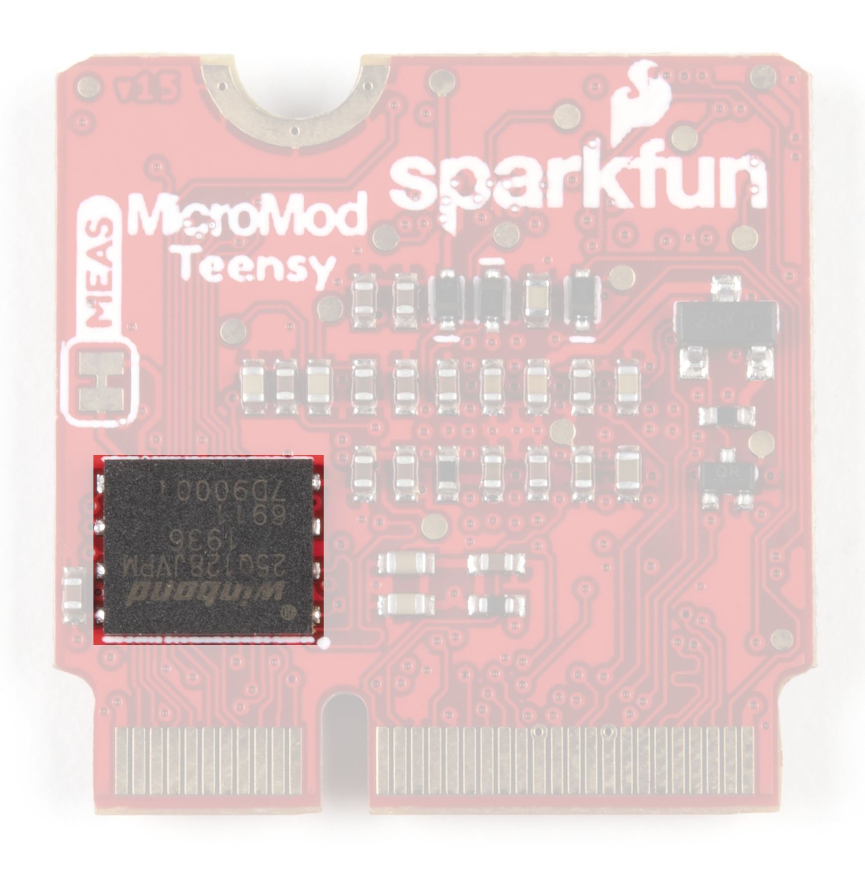
t4MMflash.png

That from SFUN image matches what I can see ... that is 16MB?


Mixed messages from FROM :: learn.sparkfun.com/tutorials/micromod-teensy-processor-hookup-guide/all

> 8MB Flash Memory (64l reserved for recover & EEPROM emulation)

> Flash IC
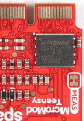
The MicroMod Teensy Processor uses the W25Q128JV-DTR serial flash memory IC from Windbond Electronics. The flash IC features 128mb of memory.

And the image:
Teensy_Processor-FlashIC.jpg
 
Last edited:
FIXED! - on product page after I left a comment - but they didn't update the 'Hookup Guide' page ... yet - added comment there ...

Code:
The Teensy Processor Board boasts some impressive computing power with an ARM Cortex-M7 processor operating at clock speeds up to 600MHz, [B]16MB Flash Memory[/B] and 1024K RAM Memory.
 
Cool ... Nate replied 'Nice! Fixed.' to my now cleared comment.

As noted - PJRC Teensy 'Card' presentation is a great reference. Seems they could make one for the MMod family.

I peeked their Forum - not the same as this one ...

BLOG POST:
Code:
Teensy Joins MicroMod!
The Teensy MicroMod Processor is now available, along with a new version of our RedBoard and a new OpenLog Artemis Kit!
...
 we have two new boards that we have been working extremely hard on, and it all starts off with the Teensy joining the 
MicroMod family. We've worked exclusively with PJRC to create a Teensy MicroMod Processor that can now drive a healthy
 assortment of MicroMod Carrier boards. This means a Teensy can now drive machine learning, weather, and GNSS 
applications - all from a single board! 
...
The SparkFun MicroMod Teensy Processor leverages the awesome computing power of the NXP iMXRT1062 chip, and pairs 
it with the M.2 MicroMod connector to allow you to plug it into your choice of compatible MicroMod Carrier Board. With the 
M.2 MicroMod connector, connecting your Teensy Processor is a breeze. Simply match up the key on your processor's 
beveled edge connector to the key on the M.2 connector, and secure it with a screw (included with all Carrier Boards).
Adding a Teensy to your desired project has never been easier!

...
 
I exchanged a couple emails with Sparkfun this morning about the specs...

Looks like they fixed the link as well from the main mircomod page as well after my post about it. @defragster - did you note our comments disappeared :)

Guess its time to do a video of the Micromod with the camera working on their ML board. @Paul - do you want us to show anything with your proto dev board?

Yes, I noted my 'now cleared comment' - there was a SPAM comment I flagged - and some other note about a bad link ... gone now - seems that was mjs513? - but I didn't look close.

Not sure I have anything to photo - but assume the Beta T_MMod's safe to show now Paul? The PCB matches 'v15' on backside corner to the photos they are showing - so not a diff PCB?

I ordered a pair of production units - and added an ATP for USB_Host to bump to free shipping as the ATP I had here seems to be well hidden.

Still showing 250+ MMod Teensy in stock.

I ordered 2 as well :). Week is still young and no one has shown what to do with it yet with any of their boards. So this should be fun.

Actually the board to show was Paul's devel carrier board. Probably not to start with :)
 
Sorry if this is a silly question - is there power regulation on the micromod board? I see USB VIN on Pin 9, 3.3V enable on Pin 4, and 3.3V on Pin 74 and on Pin 2. What is the capacity of the output regulator?
 
Sorry if this is a silly question - is there power regulation on the micromod board? I see USB VIN on Pin 9, 3.3V enable on Pin 4, and 3.3V on Pin 74 and on Pin 2. What is the capacity of the output regulator?

If understood ... the Carrier provides the power, the module is just a 'pawn'. One SFun ATP carrier w/USB_Host has extra power for stuff a T_4.1 can only use with powered HUB.

The only 3 leggy thing seen matches something on the T_4.1 - I suppose is USB_Host power switch? (possb. not that - but lost the ATP here)

SFun posted drawings that will show parts

Edit>> github.com/sparkfun/MicroMod_Teensy_Processor
 
Guess its time to do a video of the Micromod with the camera working on their ML board. @Paul - do you want us to show anything with your proto dev board?

Perfectly ok to show the blue carrier board. It's not a secret, but it also won't ever be a product.

But for a "how to" or tutorial style video, might be better to show Sparkfun's carrier anyone can actually buy.
 
Sorry if this is a silly question - is there power regulation on the micromod board? I see USB VIN on Pin 9, 3.3V enable on Pin 4, and 3.3V on Pin 74 and on Pin 2. What is the capacity of the output regulator?

MicroMod Teensy expects the carrier board to provide 3.3V power. So for the context of your question, no, it doesn't have the regulator. The part is on the carrier boards.

In a strictly technical sense, it does create 1.25V CPU power, and other lower voltage regulated power for the PLL, analog, SNVS, etc - all using the 3.3V power as input, and also a regulated voltage for internal USB use from the USB voltage.
 
Perfectly ok to show the blue carrier board. It's not a secret, but it also won't ever be a product.

But for a "how to" or tutorial style video, might be better to show Sparkfun's carrier anyone can actually buy.

Understood - but also too bad it won't ever be a product - it has everything on it that you would need from a practical standpoint, at least for me - a place for the display and the audio shield (assuming that the propshield would work with it too).
 
Understood - but also too bad it won't ever be a product - it has everything on it that you would need from a practical standpoint, at least for me - a place for the display and the audio shield (assuming that the propshield would work with it too).

Indeed too bad - that breakout was most used and useful. Maybe SFun will make a red one. Got one of their display boards but not powered as it didn't give many pins or USB_Host.
 
MicroMod Teensy expects the carrier board to provide 3.3V power. So for the context of your question, no, it doesn't have the regulator. The part is on the carrier boards.

In a strictly technical sense, it does create 1.25V CPU power, and other lower voltage regulated power for the PLL, analog, SNVS, etc - all using the 3.3V power as input, and also a regulated voltage for internal USB use from the USB voltage.

Thanks! That's what I initially thought and got tripped up (and greedy) when I saw the USB VIN.
 
Maybe SFun will make a red one.

While I'm reluctant to say anything that could be perceived as promises on Sparkfun's behalf, I will mention I exchanged emails with Nathan some time ago about an improved ML carrier, using that blue carrier board as a starting point.
 
I am playing with my own version similar to Paul’s plus other random stuff…. As for mod 3.3v VR the ones I see on their boards are rated for about 1 amp…

How much you can actually use???

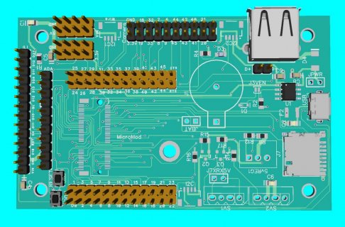
Edit: here is WIP 3d ...
screenshot.jpg
 
Congratulations, I saw the new Teensy MicroMod board on SparkFun's website this morning. Being able to build a prototype using one processor and then swap out processors as an afterthought is kind of a holy grail idea.

This makes me realize I don't really know how big the market is for things like MicroMod and Qwiic and A La Carte PCB production. I have spent hours looking at MikroElektronika's Click boards, thinking
"That's really cool but do I need I?"
Modularity like that would make sense for rapid prototyping.

I am curious. Who buys these? (Not trying to sound disrespectful here. I really don't know.) Are these for educators? People with corporate R&D budgets? Hobbyists like me? Is the goal to be able to make a prototype without soldering anything? Is the goal to have reusable parts? It's very interesting and very fun-looking to me, but I don't understand what drives the business end. Surely SparkFun is not funded by weekend mad scientists like me. I bet they get some substantial purchase orders.

Ben
 
I am playing with my own version similar to Paul’s plus other random stuff…. As for mod 3.3v VR the ones I see on their boards are rated for about 1 amp…

How much you can actually use???

Edit: here is WIP 3d ...


That reminds of the MMod Beta arrival ... All SFun MMod carrier units take USB-C connector

So perhaps more power than ever before ... but can be a letdown not having a usable cable on hand as none are included.
 
That reminds of the MMod Beta arrival ... All SFun MMod carrier units take USB-C connector

So perhaps more power than ever before ... but can be a letdown not having a usable cable on hand as none are included.

Very true. Realized I didn't have a USB-C cable when first we started with MM in this thread and had to run out to the store to pick a couple up.
 
Very true. Realized I didn't have a USB-C cable when first we started with MM in this thread and had to run out to the store to pick a couple up.

I wasn't going to mention names :) ... I was lucky and had just gotten a new phone so had gotten extra cables for the various connection matchups.

Just found something else - but still not found the ATP carrier that had decent pins and plenty of USB_Host power. I'll find it about the time the new ATP shows up :)

As far as WHY MMOD? it is an option - if there is a prebuilt carrier with needed parts the MCU module can come and go and be replaced or changed or just moved to a new project. Or PROTO with one and then for those building their own - like Paul Stoffregen, @luni, or @KurtE - a custom PCB carrier can easily get any needed pins brought out on the MMod connector and just slip in and screw down. As small as a Teensy is - the MCU module at 0.766 sq inches is smaller than 0.98 or 1.68 sq inches of a T_4.0 or a T_4.1. T_4.0 is harder to bring out USB_Host and SDIO SD card with bottom pads - and T_4.1 has SD card in a fixed position. And in spite of being smaller - moving all the other stuff off the MCU board allowed SFun to bump the onboard flash to 16MB that wouldn't fit on T_4.1 and T_4.0 only had room for a 2MB Flash.
 
As I mentioned, I ordered a couple of more of them to play with. During the beta process there were no good breakout boards that allowed you to get to all of the functionality. For example SDIO and SDCard and USB Host.

There are some interesting things with the MMOD that are different than T4 or T4.1. For example with T4.1, we have enouch CSI pins exposed to use that for 8 bit camera support, and we have some example code that works with that for the OV7670. But with the T-MOD, we don't have all of these pins, but instead we have enough of the FlexIO2 pins to do either 4 bit or 8 bit camera support. and with the Beta boards we playine with the HIMax monochrome camera with the Machine Learning board: https://www.sparkfun.com/products/16400
We have examples of this reading in this camera and then sending the frames to a display.

My breakout board I mentioned above also brings out the camera, but I used the OV7670 pin out... (avoid ribbon cable). Also has pinout for ILI cameras as well as Adafruit displays like ST7789
The T4.1 also has advantage of the ability to add extra memory...
 
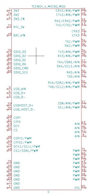
There is a lot of capability built into this board! I started making a KiCAD symbol, matched back to the Teensy 4.1 pin numbers, and labeled the additionally functionality. I realize this is what Kurt had in the excel table, but it was easier for me to visualize on the schematic. So we get: 2 SPI buses, all 3 CAN buses, 6 UARTs, 3 I2C, and a heap of Analog input and PWM output depending on how the pins are configured.

Screenshot from 2021-07-02 20-26-53.png

Note, I'm a robotics guy so the audio functionality was ignored. Also, the USB pin numbers might be incorrect, the Sparkfun schematic and hookup guide had some discrepancies.
 
Back
Top