MicroMod Beta Testing

Modified TSET to work with Beta SFun MicroMod Teensy for Windows CMDLINE build :: github.com/Defragster/Tset
>> Works with IDE
>> Best with Integrated TyCommander, when updated to support MicroMod (done with a test build)

I have a Build for Windows X64 that I built with Micromod, I put up a zip file up on my OneDrive: https://1drv.ms/u/s!Aj13xDWYbgPjibsEjQWATocwfaVTtA?e=KO8zmd
Which has those files in it. I don't know if your Virus detection code will allow it to work or not... Will remove when PR is pulled in and there is a more official build.
 
I don't know if your Virus detection code will allow it to work or not
Works with the usual Windows warnings on downloaded files. Still waiting for my MM board. But at least I can confirm that it is able to upload to a T4.1 :)
Thanks, great work! Makes life so much easier :)
 
I have a Build for Windows X64 that I built with Micromod, I put up a zip file up on my OneDrive: https://1drv.ms/u/s!Aj13xDWYbgPjibsEjQWATocwfaVTtA?e=KO8zmd
Which has those files in it. I don't know if your Virus detection code will allow it to work or not... Will remove when PR is pulled in and there is a more official build.

Just downloaded and Norton didn't like them - gives me some reputation errors. Norton is good it gave me the option to exclude and restore the files so was able to run your new version of Tycommander :)
 
@KurtE
It doesn't use SDIO - only checked the Machine learning board so far. It uses SPI with the default chip select as pin 10

Somehow makes sense. I assume they don't want to restrict the usability of those general purpose carriers to special MM processors. Lots of opportunities to do special carriers :)
 
Somehow makes sense. I assume they don't want to restrict the usability of those general purpose carriers to special MM processors. Lots of opportunities to do special carriers :)
It looks like on the ATP board which has all the pins broken out you might get away with it. On the Machine learning board they only brought out a subset of all the pins - probably since most are tied up the camera anyway but not all - not sure why they didn't bring out more of them though.
 
Somehow makes sense. I assume they don't want to restrict the usability of those general purpose carriers to special MM processors. Lots of opportunities to do special carriers :)

My problem for me with this, is that I am not sure how much of us Hobby people can hand solder one of their connectors, so it may limit how many people make breakouts...

And I wish they had some carrier board, that made it easier to experiment with:

Like maybe an ATP like board, which maybe was setup to maybe plug into a Breadboard so maybe most not > .8" .

Or one similar breakout board to this that maybe only has on it connection of MM board, USB C, and power, and buttons, leds, and then everything goes to set of pins. Not sure how many rows...

Or a board with both SDIO connections and USB host connections. Maybe have jumpers for the SDCard to allow user to jumper to use either SDIO or SPI... Plenty of space on bottom of Machine learning for this...
Again Wishlist for Machine Learning board V2:
a) SD card can be configured for SDIO or SPI
b) Camera pins, breakout to jumper pins as well, not sure if double row of pins like OV7670 Would be great if it matched that one or similar. Gives option for different cameras plus jumper points to debug.
c) USB Host support - Probably 5 pin connector like Teensy boards have for external...

...

But I know I am just dreaming. Just wish I felt comfortable with soldering something like these. Would then maybe adapt one of my T4.1 boards that has ILI9341/or 9488, and setup for OV7670 plus USB Host...
 
Actually, soldering the connector is super easy. It has two pins which conveniently fix it on the board. Just take an iron with a large flat tip and drag it across the pins using lots of solder. Then use some solder braid to clean up and you are done. Takes a minute or so. I don't have any special tools and use my 30 year old DIY solder station. Magnifying glasses help these days :)

I did a custom MM motor controller board for a solder dispenser project some weeks ago. It works nicely with my T3.2 MM board. You might have seen the video already:


So, message is: Looks MUCH more difficult than it actually is.
 
@KurtE - @luni - all
Just hooked up a Adafruit Micro SD SPI or SDIO Card Breakout Board to SDIO pins on the ATP carrier board. Ran the listfiles example in the SD library and it worked by specifying BUILTIN_SDCARD:
Code:
Initializing SD card...initialization done.
System Volume Information/
  WPSettings.dat                                  12
  IndexerVolumeGuid                               76
OV7670.bmp                                        153666
done!
and the CardInfo sketch:
Code:
Initializing SD card...Wiring is correct and a card is present.

Card type: SDHC

Volume type is FAT32

Volume size (Kbytes): 61054976
Volume size (Mbytes): 59624

EDIT: Well one more thing off my list of things to check out. Oh btw it does have a card detect pin but I have not tried it yet.
 
Thanks @luni, May have to try it. I was wondering if there were index pins. Should have looked more carefully. Still think one good out of two or three may be as good as I will get... But then if I order 10 boards, it gives me several extras to screw up on as I often only make one or two ;)

Sparkfun - a couple of other suggestions: maybe a version of the MicroSD adapter like: https://www.sparkfun.com/products/544 that has the pins to match the SPI pin order of the ATP :D
Likewise maybe the: https://www.sparkfun.com/products/12941 version to match the SDIO...

Think we cross posted. The interesting thing with the Adafruit one is that it can be run as SPI or SDIO depending on your wiring.
 
Quick note : using the prior posted NewPinTest it showed pin 10 ( also CS? ) as the card insert detect.
That would work on SD pins as well for ID - though I did not do that.

@KurtE - pulled down the newer non-debug TyCommnader and it started after the typical 'Unblock' - or just power through the blocking with 'More ... - run anyway'

Pin 10 is shown on ATP board as CS and not as card insert detect? Not sure how that is getting picked up. I have not seen card insert detect on any pinout's. Confused
 
@all sounds good.

@mjs513 yes cross posted... I am about to switch back over to ATP board to start playing. Will cable in SDCard (Don't have the SDIO version yet. Could adapt something..

Working on MTP stuff, now have it formatting the SD card. More for other thread.
 
@all sounds good.

@mjs513 yes cross posted... I am about to switch back over to ATP board to start playing. Will cable in SDCard (Don't have the SDIO version yet. Could adapt something..

Working on MTP stuff, now have it formatting the SD card. More for other thread.

Have some errands to run then want to play with MTP for awhile - out of ideas on the HB01. I know we are getting data and I can print it but not sure how to get it into display format :)
 
Side note/question: I am 99% sure I know the answer, but that I would ask.

Is there a known way to detect which host board your MM board is plugged into... I am almost certain: NO.

Several years ago, I know I was playing with a different board (Maybe Beagle Bone Black?) where each board might have a small SPI ROM with an ID... Probably way overkill for here.
 
P#54 shows:
Code:
On MMod DataLogger and MACHINE LEARNING PIN 10 is the CARD INSERT says NewPinTest!

And p#34 has : NewPinTest sketch

I wondered about Carrier Board detect too. Nothing Easy - would be piecemeal for some boards maybe? In above posts some have diff pins held high on start - i2c or other - Display has i2c hardware for joystick and buttons.
Code:
Note:
> Machine Learn board has pullups on 18/19 { i2c }
> ATP does not have Pullups on 18/19
> Logger Carrier shows #22 again and these pins HIGH on PullDown Start : 10,18,19,22,41,42

Just tested TSET and above Release TyCommander to build NewPinTest in SublimeText for Display board - IT WORKS! It shows it's unique HIGH pins : 4,10,18,19,29,40,42
Code:
  PULLDOWN :: TEST to 3.3V
  0,0,0,0,
d#=4 val=1,0,0,0,0,0,
d#=10 val=1,0,0,0,0,0,0,0,
d#=18 val=1,
d#=19 val=1,0,0,0,0,0,0,0,0,0,
d#=29 val=1,0,0,0,0,0,0,0,0,0,0,
d#=40 val=1,0,
d#=42 val=1,0,0,0,

ALSO:
PULLUP :: TEST TO GND
  d#=2 val=0

ADDED NOTE: Display Carrier DOES NOT show any pin CHANGE on SD card insert!
 
Last edited:
Just looked that the Big display Carrier board does use the SDIO pins :D Don't have one... Note: their schematic and parts don't show anything for insert pin connection... So probably not.
 
Just looked that the Big display Carrier board does use the SDIO pins :D Don't have one... Note: their schematic and parts don't show anything for insert pin connection... So probably not.

Indeed confirmed with NewPinTest in p#166 above : No pins change on Display Carrier SD insert/remove. Also updated the PullUp test shows pin#2 held low. So there is possibly a 'signature' for each board reading GPIO in setup For pins held High and Low.
 
Side note/question: I am 99% sure I know the answer, but that I would ask.

Is there a known way to detect which host board your MM board is plugged into... I am almost certain: NO.

Several years ago, I know I was playing with a different board (Maybe Beagle Bone Black?) where each board might have a small SPI ROM with an ID... Probably way overkill for here.

The Raspberry PI hat system has this. They hook up a small EEPROM memory to the secondary I2C bus, and via I2C, you can read the information. Unfortunately IMHO, they made a fundamental design flaw in that there can only be one hat installed on a system. Coming from an Arduino background where I often stacked different shields, this restriction made no sense. I think at the time, I wanted to stack a display and a motor driver.
 
RE: Hat/Carrier ID - indeed adding anything would take board space and use up a pin or more or require some 'bus' to be polluted. Or in that rPi hat case - require more effort.

Looking at NewPinTest - the code is not doing test change as 'implied' - but it runs the compiled test hardcoded "xx=#" and the input processing is halfway functional - i.e. broken in some state where there was 'Work In Progress' ... from the loglow T_4.0 breakout days ...

Question: What is the PinMode() to return the pin to Hi-Z neutral state?
 
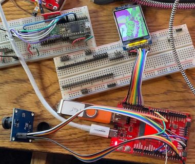
This afternoon I started playing with the ATP board with the MicroMod... I first hooked up an ST7735 display along with its SD card reader. Got that to work, with the non standard pins. Left pin 10 for CD so it would work with the MTP stuff...

I then added a OV7670 and started hacking on the OV7670 code I have in a hacked up library doing GPIO reads...

Making some progress, Here is a picture. Hopefully I obscured the MMOD module sufficiently...
TMOD_OV7670_tft.jpg

It is grabbing some data, does not look correct, could be timing or wrong pin order or....
One thing I had to remember that was using GPIO6 on T4 or T4.1, but now using GPIO7... Will need to remember that when I change the DMA code.

I have not updated the code on github, but if curious,
 

Attachments

  • CameraDisplay_tft.zip
    40.8 KB · Views: 44
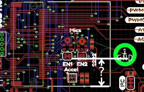
I started a quick carrier board design which brings out the pins and attempts an alternate 4 bit camera connection which should leave all the audio pins available.

Does anyone know the correct distance from the M.2 standoff from the edge of the PCB?

m2spec.png

Trouble with M.2 is searches turn up tons of PC consumer questions and white box builder info. Sparkfun's info is heavy on Eagle examples, light on specs for non-Eagle usage...
 
I started a quick carrier board design which brings out the pins and attempts an alternate 4 bit camera connection which should leave all the audio pins available.

Does anyone know the correct distance from the M.2 standoff from the edge of the PCB?

View attachment 24331

Trouble with M.2 is searches turn up tons of PC consumer questions and white box builder info. Sparkfun's info is heavy on Eagle examples, light on specs for non-Eagle usage...

I have Eagle installed but not 100% sure how to use it. But using the dimension tool looks like about 21.59mm from the center of the mounting to the middle of the M.2 connector and 17.78 from the middle to the outline for the connector on the board layout. But you probably need something more accurate. Don't know if this helps.
 
Back
Top