Kuantronic
Member
Hi everyone 
This is my first forum post here and it's about a personal project I'm working on right now. I want to play with the T3.6 with a few projects in mind but the wiring on the breadboard can get quite big and annoying for me. This is epically true when I start combining features from different projects together. At the same time, I'm learning Altium Designer so I decided to design a custom T3.6 board on it based on the available info from PRJC. This way, I'm basically killing two birds with one stone with this project. As for where I am on the progress, I'm still copying the components onto the Altium schematic and making the pin mappings on the MK66FX uC.
A quick backstory about me and the Teensy. Not too long ago, I first got a Teensy 3.2 to try it out with luni64's teensyStep library and my stepper motor. Absolutely loved the speed of it! Way faster than the 4000 steps/sec limit with the AccelStepper library on my custom made Arduino Mega board! The T3.2 is the first microcontroller board I used outside of the usual 8bit 16 MHz Arduino boards.
I know I'll need to purchase the bootloader chip from PRJC for the board to work which I'll happily do. For the board design itself, the dimension will be at least 100mmx100mm in dimension. Might make it a 4-layer board (will be a first for me as I have only done 2-layers before). Once the board design is done, I plan to send the Gerber to JLCPCB for manufacturing. I also plan to use their SMT service to solder a lot of the basic components on for me like chip resistors. The rest I'll solder myself.
There are several things I plan to add to the board design; some of which are listed below:
I'm open to suggestions for other things I should add.
Now I do have a few questions about the schematic if Paul or anyone else might be able to answer:

This is my first forum post here and it's about a personal project I'm working on right now. I want to play with the T3.6 with a few projects in mind but the wiring on the breadboard can get quite big and annoying for me. This is epically true when I start combining features from different projects together. At the same time, I'm learning Altium Designer so I decided to design a custom T3.6 board on it based on the available info from PRJC. This way, I'm basically killing two birds with one stone with this project. As for where I am on the progress, I'm still copying the components onto the Altium schematic and making the pin mappings on the MK66FX uC.
A quick backstory about me and the Teensy. Not too long ago, I first got a Teensy 3.2 to try it out with luni64's teensyStep library and my stepper motor. Absolutely loved the speed of it! Way faster than the 4000 steps/sec limit with the AccelStepper library on my custom made Arduino Mega board! The T3.2 is the first microcontroller board I used outside of the usual 8bit 16 MHz Arduino boards.
I know I'll need to purchase the bootloader chip from PRJC for the board to work which I'll happily do. For the board design itself, the dimension will be at least 100mmx100mm in dimension. Might make it a 4-layer board (will be a first for me as I have only done 2-layers before). Once the board design is done, I plan to send the Gerber to JLCPCB for manufacturing. I also plan to use their SMT service to solder a lot of the basic components on for me like chip resistors. The rest I'll solder myself.
There are several things I plan to add to the board design; some of which are listed below:
- 4 or 6 TMC2209 stepper driver mounts for easy setup and controlling up to that amount of stepper motors
- Groove I2C connector and Sparkfun Qwiic connector for 5V I2C and 3.3V I2C respectively with bi-directional logic level shifter between them. For easy connection to I2C devices
- Audio input & output for easy plug and play with the Teensy Audio library
- CR2032 battery holder for RTC feature
- 4-pin PC fan header for 5V cooling fans
- Maybe an ethernet port
- Any other connector for easy connections to modules like the HC-05 Bluetooth module.
I'm open to suggestions for other things I should add.
Now I do have a few questions about the schematic if Paul or anyone else might be able to answer:
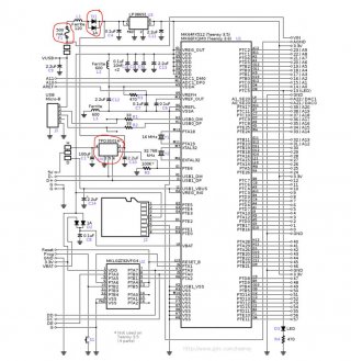
- D1 on the schematic shows two diodes in parallel. Why is that? Can't it just be a single diode?
- I don't plan to add F1. I believe it should be fine? I haven't added fuses for my other custom Arduino board and it never gave any issues
- Why do you need a second 3.3V regulator (TPD3S014) for what I assume is the other USB port? Also why is it a different model than U3?
- Can I swap the voltage regulator U3 for AP7365-33EG-13? This is the 3.3V regulator I have on-hand right now.


