StanfordEE was able to get a beautiful 150 MHz square wave from a Teensy 4.0. All I need is 25 MHz square wave from the Teensy 4.1 but everything I try looks like trash... Here is my code:
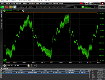
But this is the waveform I measure on pin 34:

The frequency is roughly double the target frequency with 10 ns rise and fall times.
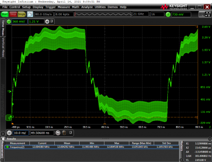
If I use delayNanoseconds(20) instead of the sets of NOPs then the problem is the opposite:

I.e., the frequency is now half of the target frequency but the 10 ns rise and fall times remain.
I don't know why NOPs & delayNanoseconds are 2x off from what they should be but I'd like to solve the slew rate issue first: In this post, Paul enables fast slew rate mode on the Teensy 3.5:
The Teensy 4.1 product page also mentions slew rate limiting:
How do I do this on the Teensy 4.1?
Code:
#define NOP __asm__ __volatile__ ("nop\n\t")
#define PIN_A  34 //Pin 34 on Teensy 4.1. GPIO 7.29.
#define PIN_B  35 //Pin 35 on Teensy 4.1. GPIO 7.28.
#define PIN_C  36 //Pin 36 on Teensy 4.1. GPIO 7.18.

//Takes binary # between 000 & 111 (0–7), where LSB -> PIN_A, ..., MSB -> PIN_C,
//and sets the respective bits in the register so those pins output HIGH:
void set3BitsInPort7(uint32_t threeBitsToSet) {
  GPIO7_DR_SET = ((threeBitsToSet>> 0) & 1) << CORE_PIN34_BIT  | //PIN_A
                 ((threeBitsToSet>> 1) & 1) << CORE_PIN35_BIT  | //PIN_B
                 ((threeBitsToSet>> 2) & 1) << CORE_PIN36_BIT; //PIN_C
}

//Takes binary # between 000 & 111 (0–7), where LSB -> PIN_A, ..., MSB -> PIN_D,
//and clears the respective bits in the register so those pins output LOW:
void clear3BitsInPort7(uint32_t threeBitsToClear) {
  GPIO7_DR_CLEAR = ((threeBitsToClear>> 0) & 1) << CORE_PIN34_BIT  | //PIN_A
                   ((threeBitsToClear>> 1) & 1) << CORE_PIN35_BIT  | //PIN_B
                   ((threeBitsToClear>> 2) & 1) << CORE_PIN36_BIT; //PIN_C
}

void setup() {
  pinMode(PIN_A, OUTPUT);
  pinMode(PIN_B, OUTPUT);
  pinMode(PIN_C, OUTPUT);
  noInterrupts();
  clear3BitsInPort7(7); //Make PIN_A, PIN_B, & PIN_C LOW.
  delay(1000);
}

void yield() {

}

void loop() {
  while(1) {
    set3BitsInPort7(7); //Make PIN_A, PIN_B, & PIN_C HIGH.
    //delay((n+1)*1/600e6) = delay(20e-9) -> n = 11:
    NOP;
    NOP;
    NOP;
    NOP;
    NOP;
    NOP;
    NOP;
    NOP;
    NOP;
    NOP;
    NOP;
    clear3BitsInPort7(7); //Make PIN_A, PIN_B, & PIN_C LOW.
    //delay((n+1)*1/600e6) = delay(20e-9) -> n = 11:
    NOP;
    NOP;
    NOP;
    NOP;
    NOP;
    NOP;
    NOP;
    NOP;
    NOP;
    NOP;
    NOP;
  }
}
But this is the waveform I measure on pin 34:

The frequency is roughly double the target frequency with 10 ns rise and fall times.
If I use delayNanoseconds(20) instead of the sets of NOPs then the problem is the opposite:

I.e., the frequency is now half of the target frequency but the 10 ns rise and fall times remain.
I don't know why NOPs & delayNanoseconds are 2x off from what they should be but I'd like to solve the slew rate issue first: In this post, Paul enables fast slew rate mode on the Teensy 3.5:
Code:
void setup() {
  pinMode(13, OUTPUT);
  PORTC_PCR5 &= ~0x04; // disable slew rate limit
  noInterrupts();
  while (1) {
    digitalWriteFast(13, HIGH);
    digitalWriteFast(13, LOW);
    digitalWriteFast(13, HIGH);
    digitalWriteFast(13, LOW);
    digitalWriteFast(13, HIGH);
    digitalWriteFast(13, LOW);
  }
}
void loop() {
}
The Teensy 4.1 product page also mentions slew rate limiting:
This optional feature greatly reduces high frequency noise when long wires are connected to digital output pins. The rate of voltage change on the pin is slowed. The extra time is only nanoseconds, which is enough to lower undesirable high frequency effects which can cause trouble with long wires.
How do I do this on the Teensy 4.1?

