TLC5940 voltage

Status
Not open for further replies.

djex81

Active member
Hello everyone. I have a question with using the TLC5940 LED driver with a Teensy 3.6 as outline here https://www.pjrc.com/teensy/td_libs_Tlc5940.html . On that page it says to use 5 volts on the VCC, DCPRG and BLANK pins with the BLANK pin having a 10k pullup resistor. My concern is the 5 volts on the BLANK pin as it's also connected to pin 4 on the Teesny. I know Teensy 3.6 is not 5 volt tolerant and so will this be an issue if 5 volts is supplied to the BLANK pin and also connected to the Teensy on pin 4? I think it should be fine because of the 10k resistor but I'm inexperienced and would like confirmation before I try it.

Alternatively should I just power everything with 3.3 volts since the TLC5940 has a range of 3 - 5.5volts for VCC?
 
yes that will be an issue for as you said the teensy is not 5v tolerant.

You need a level shifter between the teensy and TLC5940.
Example
Higher quality example (likely better rise/fall times, I'd recommend one like this)


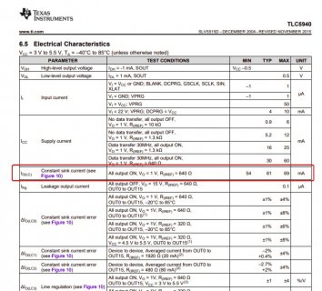
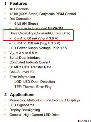
Oh just read the last part and confirmed with the datasheet, yeah it seems you're right it can be driven with 3.3v so that's good! Just note this reduces the overall current capacity of the chip significantly:
chrome_rbmhht13iu.jpg
chrome_e66gQwRtxN.jpg

I'm having a hard time reading this datasheet, it seems like it's suggesting 60mA total for the whole chip, but it's possible I'm wrong and it's 60mA per output.

If driving with 3.3v you must be sure to protect against brown-outs of the chip, 0.3v overhead isn't much. If this is a final installation somewhere I'd put a local 3.3v regulator right next to the chip with some capacitance nearby to ensure total stability.
 
yes that will be an issue for as you said the teensy is not 5v tolerant.

You need a level shifter between the teensy and TLC5940.
Example
Higher quality example (likely better rise/fall times, I'd recommend one like this)


Oh just read the last part and confirmed with the datasheet, yeah it seems you're right it can be driven with 3.3v so that's good! Just note this reduces the overall current capacity of the chip significantly:

I'm having a hard time reading this datasheet, it seems like it's suggesting 60mA total for the whole chip, but it's possible I'm wrong and it's 60mA per output.

If driving with 3.3v you must be sure to protect against brown-outs of the chip, 0.3v overhead isn't much. If this is a final installation somewhere I'd put a local 3.3v regulator right next to the chip with some capacitance nearby to ensure total stability.

Thanks for the reply. Doing a quick search it does look like that's 60mA per channel which is completely fine in my case as I'm not using LEDs that draw any more than 25mA each. Like you suggested I'm going to use a regulator to prevent voltage drop.
 
Status
Not open for further replies.
Back
Top