KISS problem setting Millis timed pulses during ON time

Status
Not open for further replies.
good morning,

i played a bit with the ElapsedMillis();

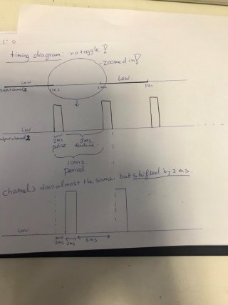
so far i got two signals that are shifted please see pictures:
View attachment 24520
View attachment 24521
View attachment 24522

but the pulse train stops after a period of time of 1 second and doesnt repeat.


i removed the functionRepetition_Polarity_Change_Emag()
and used if else statements after the independent on off.

could someone elaborate the ElapsedMillis why it doesnt work inside a nested if statement as in the CODE3?
it just defies logic for me, but it has to do with the global variable i think of ElapsedTimeIndependent and is overwritten?

this code works and creates a pulsetrain for 1 second with 12ms period. 2ms of this period is the pulse HIGH the other signal for unknown reason stays low.

any advice?
Code:
//Defining the pins

const int INB_AntiClockwise       = 2;
const int INA_Clockwise           = 3;

unsigned long previousMillis = 0;

unsigned long Timestamp = 10; //10ms per division
unsigned long PulseWidth = 2; //variable for setting the pulse
unsigned long timer;
unsigned long timer2;
bool VNH5019 = LOW;   //it has not effect changing this from int to byte

unsigned int ON_Time1 = 1000;                     //ON Time
unsigned int OFFTime1 = 1000;                     //OFF Time

elapsedMillis ElapsedTime;                         //ElapsedMillis for pulses and period
elapsedMillis ElapsedTimeIndependent;
elapsedMillis pulse;                               //ElapsedMicros

void setup()
{
  Serial.begin(9600);

  pinMode(13, OUTPUT); digitalWrite(13, LOW);
  pinMode(INB_AntiClockwise, OUTPUT); digitalwrite(INB_AntiClockwise, LOW);
  pinMode(INA_Clockwise, OUTPUT); digitalWrite(INA_Clockwise, LOW);

}

void loop()
{


  if ((VNH5019 == HIGH) && (ElapsedTimeIndependent >= OFFTime1)) //OFFTime first
  {
    VNH5019 = LOW;
    digitalWrite(INA_Clockwise, LOW); digitalWrite(INB_AntiClockwise, LOW);  //doesnt matter high or low both need to be HIGH or LOW.
    ElapsedTimeIndependent = 0;//[COLOR="#FF0000"]this resets the elapsedTime[/COLOR]
  }
  else if ((VNH5019 == LOW) && (ElapsedTimeIndependent >= ON_Time1)) //ONTime 1 second
  {
    //Serial.println("On Time");//so that i know i am in this part of the else if statement
    VNH5019 = HIGH;
    //   Repetition_Polarity_Change_Emag();  //this functions sets the PulseWidth and the Period //here I call the function

  }
  else if (ElapsedTimeIndependent >= (timer + Timestamp)) 
  {
    digitalWrite(INA_Clockwise, HIGH);
    digitalWrite(INB_AntiClockwise, LOW);
    timer = ElapsedTime + 2; //pulse is shifted with 2ms
    timer2 = ElapsedTime;
    //duration of the Pulse is set here.
    Serial.println("TimeStamp");
  }              // Sets the Output Low for the pulse
  else if ((pulse) > (timer + Timestamp)) 
  {
    digitalWrite(INA_Clockwise, HIGH);
    // Turn the output back to High

  }
  else if ((pulse) > (timer2 + Timestamp)) //create a shift between the INA and the INB
  {

    digitalWrite(INB_AntiClockwise, HIGH);
    // Turn the output back to High


  }
      

}
 
Again you've posted code which does not compile when copied into Arduino. In this case the mistake appears to be "digitalwrite" (the W not capitalized) which is an easy problem to fix. Still, I wonder if this really is code you actually used on your Teensy? Why is this sort of error present if you simply copy the code in Arduino and paste it here to the forum?

Still, I'm trying to look at this again and help if I can.

First, to answer your specific questions from msg #25:


Question1: could someone elaborate the ElapsedMillis why it doesnt work inside a nested if statement as in the CODE3?

elapsedMillis does indeed work from inside nested if statements. The problem is not with elapsedMillis.


Question2:
it just defies logic for me, but it has to do with the global variable i think of ElapsedTimeIndependent and is overwritten?

The problem is larger than any one specific variable or conditional expression in the code.

Essentially there are 2 large problems here.

1: Your coding approach is not good.

2: I can't understand from the words you've written what the program is supposed to do.

Regarding #2, perhaps you could draw on paper or graphics software a picture of the desired result?
 
Here is an example which can hopefully show you a better way to approach this sort of programming task.

This a programming paradigm called a state machine. It is a widely used approach in computer programming because it provides a clear way to design your code to meet requirements.

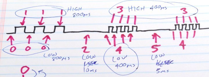
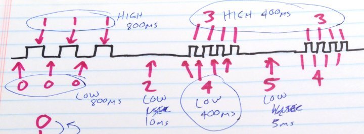
First, start with a picture of your desired waveform and assign a state number of each portion of the waveform. A clear picture of every state of your designed waveform is the critical key to successfully coding a state machine program. To keep this simpler, here's a waveform which begins with 3 slower pulses, then has an off time, then repeats a burst of 4 faster pulses with a shorter off time between each burst.

statemachine1.jpg

As you can see, I assigned 6 different states. Each pulse has 2 states, and the 2 off times are their own state.

Using a single variable for the overall state of your waveform is my primary recommendation. Structure the first level of if-else conditions around this state variable.

In this example, a secondary state variable counts the number of pulses. You should strive use as few variables as possible. DO NOT add more state variables unless they are truly necessary. The most states, the harder your code is to write and test and debug.

Usually only 1 elapsedMicros is needed. Do not add more.

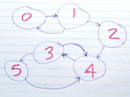
Before you start coding, it's often helpful to draw a map of which states can transition to which other states. This diagram can help you to write correct code because each circle becomes a 1st level "if" and each arrow becomes a 2nd nested "if" inside the condition for the state where it originates (and the code within that 2nd level "if" depends on where the arrow points).

statemachine2.jpg

For this example, when in state 2, the only possible outcomes from running loop() are to remain in state 2 or to transition to state 4. When in state 3, the possible outcomes from loop() are to remain in state 3 or transition to state 4 or state 5. Knowing which states can transition to which other states is critically important. Each possible transition to a different state becomes a nested "if" condition.

Here is the code to implement this simple example.

Code:
int state;
int pulseCount;
elapsedMicros usec;

void setup() {
  // begin state 0
  pinMode(2, OUTPUT);
  digitalWrite(2, LOW);
  while (!Serial && millis() < 5000) ; // wait up to 5 seconds for Arduino Serial Monitor
  // initial state:
  state = 0;
  pulseCount = 0;
  usec = 0;
  Serial.println("Begin program at state 0");
}

void loop() {

  switch (state) {
    case 0: // low portion of slower pulse
      if (usec >= 800) {
        // transition to state 1
        digitalWrite(2, HIGH);
        pulseCount = pulseCount + 1;
        usec = 0;
        state = 1;
        Serial.println("begin state 1");
      }
      break;

    case 1: // high portion of slower pulse
      if (usec >= 800) {
        if (pulseCount < 3) {
          // transition back to state 0 if not enough pulses delivered
          digitalWrite(2, LOW);
          usec = 0;
          state = 0;
          Serial.println("begin state 0");
        } else {
          // transition to state 2 after enough slow pulses
          digitalWrite(2, LOW);
          usec = 0;
          state = 2;
          Serial.println("begin state 2");
        }
      }
      break;

    case 2: // off time between slower & faster pulses
      if (usec >= 10000) {
        // transition to state 4 to start fast pulsing
        digitalWrite(2, LOW);
        usec = 0;
        pulseCount = 0; // reset pulsecount, since states 3+4 will count pulses
        state = 4;
        Serial.println("begin state ");
      }
      break;

    case 3: // high portion of faster pulse
      if (usec >= 400) {
        if (pulseCount < 4) {
          // transition back to state 4 if not enough pulses delivered
          digitalWrite(2, LOW);
          usec = 0;
          state = 4;
          Serial.println("begin state 4");
        } else {
          // transition to state 5 after enough fast pulses
          digitalWrite(2, LOW);
          usec = 0;
          state = 5;
          Serial.println("begin state 5");
        }
      }
      break;

    case 4: // low portion of faster pulse
      if (usec >= 400) {
        // transition to state 3
        digitalWrite(2, HIGH);
        usec = 0;
        pulseCount = pulseCount + 1;
        state = 3;
        Serial.println("begin state 3");
      }
      break;

    case 5: // off time between bursts of faster pulses
      if (usec >= 5000) {
        // transition back to state 4 to restart fast pulsing
        digitalWrite(2, LOW);
        usec = 0;
        pulseCount = 0;
        state = 3;
        Serial.println("begin state 3 (starting new burst of pulses)");
      }
      break;

    default: // state should never be anything other than 0 to 5
      setup();
  }
}

The most important concept is to use a clear structure in the code, where each of the first level conditions corresponds to the current state. Within each current state, every second level "if" condition corresponds to exactly 1 of the possible transitions to a different state. For a state like state 3, there are two "if" conditions because state 3 can end with a transition to either state 4 or to state 5.

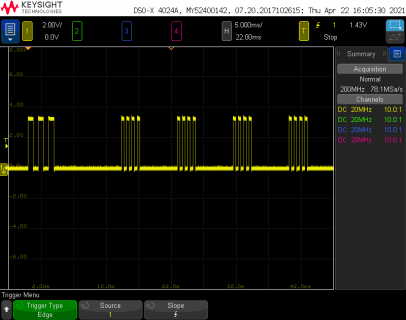
Here is the waveform the code creates.

file.png

While there are many possible way to write your code, I highly recommend you follow this state machine approach. Drawing the waveform on paper, assigning states to each portion, and then drawing the state transition diagram may seen like "trivial" work, but you should do those steps before writing any code. The state transition diagram is particularly important, because as you can see in this example, each item on the diagram becomes a 1st tier or 2nd tier "if" condition. Planning the state machine properly can give you a way to easily write code which will be correct. That is why this state machine programming technique is so widely used.

If you follow this approach and avoid the temptation to add unnecessary state variables, I'm sure you can find a path towards success.

While I used numbers 0 to 5 in this simple example, it is common practice to give a name to each state. That can help if your goals require a larger number of states.

But for communicating your project goals on this forum or on Facebook, I'm afraid I do not have a well defined process like the state machine programming paradigm. Writing clearly in English is difficult. Maybe try drawing pictures of the waveform your program is attempting to create. A diagram like I showed in this example can help communicate. We can try to help you, but without a clear idea of what your program should do, it is very difficult to help.

Hopefully this simple example at least helps you start on a path to success using the state machine programming approach?
 
While the state machine structure (and drawing the diagrams for planning your code) is by far the most important point, you might also consider a couple minor details about use of elapsedMicros.

Generally your "if" conditions checking elapsedMicros should look like this, where you check if the elapsed time has become greater than a specific constant or value of a configuration variable.

Code:
    case 4: // low portion of faster pulse
      [B]if (usec >= 400) {[/B]
        // transition to state 3
        digitalWrite(2, HIGH);
        [B]usec = 0;[/B]
        pulseCount = pulseCount + 1;
        state = 3;
        Serial.println("begin state 3");
      }
      break;

I specifically would advise against this sort of structure.


Code:
  else if (ElapsedTimeIndependent >= [B][COLOR="#B22222"](timer + Timestamp)[/COLOR][/B])

Follow an approach where you either set the elapsedMicros variable back to zero, or subtract a constant from it, when you transition to a different state. Then within that state, your "if" conditions checking elapsed time should be kept simple. Only check if the time has become greater than (or equal or greater than) a constant or configuration setting.

While writing code which computes thresholds like "(timer + Timestamp)" is technically legal code, this sort of approach quickly becomes very confusing. When coupled with an increasing number of ad-hoc if-else conditions and too many redundant state variables, it turns into a terribly difficult and confusing mess. This of this as trying to shoot a moving or changing target! Keep the target only a simple fixed number.

Use the state machine approach with a clearly drawn state transition diagram, so your code structure is clearly determined by the states and their allowed transitions. Together with only setting the elapsedMicros as needed at state transitions and testing it against only a simple constant (no math of the threshold, only a fixed number) your code will be much simpler to understand and debug.
 
Paul,

Many thanks for your time, understanding, and your explanations.
Really appreciated!

The state machine: I only worked with small examples till now. Also including simple if statements.
I was confused because one of the posts, there was a suggestion that I should reduce the number of elapsedMillis. I was wondering and looking up the various code examples that I lost track.

Also I was gradually becoming more and more confused, I didn’t know that substracting a value from elapsedMillis could benefit me in this case.

I used in other code the case structure for a 6pst switch. To select between different menus. I didn’t think this could be adapted for creating signals. But that’s another topic in total.

As you can see I have a shallow understanding of programming, or a large imagination missing out the smaller details in this case.


Back to the topic state machine
———

my program consists of three states

First state OFF: both outputs 2,3 are to be LOW during this time.

Second state ON: ON can only be reached if the condition of state 1 is fulfilled/reached.

Third state: Period:// i am confused here because i don't know if the approach is right or where to set the period. here or in the other state. so i splitted up the third state into fourth state Pulse and fifth state dead time for Output2. so correct me if i am wrong, please with red. i thought this makes sense in how to work with the State Diagram. As i said i am confused.and i dont know if i am doing it corectly

Fourth state

Output 2 requires to HIGH for 2ms

Fifth state:
Output 2 requires to be LOW for 8ms
----------------------------------- OUTPUT 3
Fourth State
Output 3 LOW 2ms

Fifth state:
Output 3 HIGH 2ms

Sixth State:
Output 3: LOW 6ms.
----------------------------------

State Diagram.jpg
signal diagram for StateDiagram.jpg

------------------------------------------------
final question:
OUTPUT 2:
State1:if ElapsedMillis>=OFFTime
State2:else if ElapsedMillis>=ONTime
State3:else if (ElapsedMillis>=Period ) 10ms
State4:if(ElapsedMillis>Pulse) 2ms OUTPUT2 =HIGH;
State5:if(ElapsedMillis>Deadtime) 8ms OUTPUT2 =LOW;

OUTPUT3:
State1:if ElapsedMillis>=OFFTime
State2:else if ElapsedMillis>=ONTime
State3:else if (ElapsedMillis>=Period ) 10ms
State4:if(ElapsedMillis>Pulse) 2ms OUTPUT3=LOW;
State5:if(ElapsedMillis>) 2ms OUTPUT3=HIGH // i am confused with the OUTPUT2 State 4 pulse and deadtime because would like to shift it with 2ms
State6:if(ElapsedMillis>Deadtime


if the Period is set to a higher value then the ON Time.
Were in the code do i check for this condition? between state 2 and state 3?
where do i reset the elapsedMillis =0;
using multiple elapsedMillis isnt that easier?

so i have to program like this?

thanks:)
 
Last edited:
not easy to follow - these questions hit me to look at it::

when : "my program consists of three states" then lists up to the sixth state? And notes on OUTPUT 2 and 3 - but OUTPUT 1 not indicated?

How many total outputs are there?

Are the OUTPUTs independent of different inputs?

The drawings seem to show only two outputs (pin # 2 & 3) and the difference is that Once out#2 is started then out#3 needs to start 2ms after #2 is started and also out#2 goes off? ...


So that indicates 2 OUTPUTS that depend on the same INPUT or trigger but just have different 'lifetimes' - where that would suggest the listed states are close to correctly defining the system.

Your system is different than Paul's DEMO of a single output cycling at two different rates.

Your case is two outputs that trigger on the same condition (?) and then progress on the same timeline but at different rates (?).

Draw a line for each output, where either one needs to change, this is a new state - where it runs on a single elapsedMicros variable.

Quick guess ( a shame the shadowed images are not easier to read )

Starting in state #0 , with :: elapsedMicros T; // defined but not needed in state #0 or #1

#state : Action
#0 : Turn off out #2 and out #3 and set state #1
#1 : if ( triggering input ) THEN:: zero time T, ON output2 and set state #2
#2 : if T>= 2ms then off output 2 and on output 3, zero time T, and set state #3
#3 : if T>= 2ms then off output 3 , zero time T, and set state #4
#4 : if T>= 6ms then on output 2 , zero time T, set state #2

That should run forever in that pattern that seems to match the second 'timing diagram'

If at any point they need to stop (Loss of triggering input detected in states #2, #3, #4 perhaps) then that needs to be accounted for to return the system back to state #0 to set both outputs off
 
Hi

i am trying to drive the direction of the current with the VNH5019
over the OUTPUT Pins 2,3 from my teensy4.1

sorry for the shadow on the pictures:

So that indicates 2 OUTPUTS that depend on the same INPUT or trigger but just have different 'lifetimes' - where that would suggest the listed states are close to correctly defining the system.
Correct.

Your system is different than Paul's DEMO of a single output cycling at two different rates.

Your case is two outputs that trigger on the same condition (?) and then progress on the same timeline but at different rates (?).
YES
Draw a line for each output, where either one needs to change, this is a new state - where it runs on a single elapsedMicros variable.

Quick guess ( a shame the shadowed images are not easier to read )

Question: so if i draw the Statemachine on paper: does the State itself resembles a Change?

Starting in state #0 , with :: elapsedMicros T; // defined but not needed in state #0 or #1 //this is OFF i think

#state : Action
#0 : Turn off out #2 and out #3 for 1 second and set state #1 for
#1 : if (
triggering input
) THEN::
what do you mean by then(do something >=?) or substract elapsedmillis=?
zero time T
This means ElapsedMillis=0?
, ON output2 and set state #2
does this not occur in state 2?
#2 : if T>= 2ms then off output #2 and on output #3, zero time T, and set state #3
#3 : if T>= 2ms then off output 3 , zero time T, and set state #4
#4 : if T>= 6ms then on output 2 , zero time T, set state #2
Still Confused here, i have drawn 5 A4 papers, which i dont want to post, because I dont understand how to do it.

so when is the elapsedmillis set to Zero=? i want to know this for understanding. and when do I substract. because these two Actions really matter.

That should run forever in that pattern that seems to match the second 'timing diagram'
Yes.


If at any point they need to stop (Loss of triggering input detected in states #2, #3, #4 perhaps) then that needs to be accounted for to return the system back to state #0 to set both outputs off
I didnt understand this.
 
Last edited:
Anything after a 'then' means :: Write code to do indicated actions like (YES) :: ElapsedMillis T=0;

The actions are done "at that time in code" off or on as indicated and change the state THEN and break; After that, all is ready to enter the next state ... which waits for its entry condition indicated.

The final statement is a question not answered :: Once started does this run FOREVER, or must it monitor the 'triggering input' and STOP toggling the outputs?

If it runs forever then that is all.

BUT:: If at any point they need to stop (Loss of triggering input detected in states #2, #3, #4 perhaps) then that needs to be accounted for to return the system back to state #0 to set both outputs off

That could be :: if ( no trigger to continue ) { set state #0; break; } before testing or doing anything else in that state.
 
Third state: Period:// i am confused here because i don't know if the approach is right or where to set the period.


Indeed this is very wrong.

The main problem is you did not identify the individual segments of your waveform diagram and label each as its own state.

Without key detail of each state clearly representing each small segment of your waveform, you started just making up states starting with "state 3: period", and then started trying to imagine ways of not following this state machine approach. That is absolutely the wrong way. The "period" of your waveform must be at least 3 states, maybe 4. First you need a state for pin 2 driven high. Then maybe a dead time state where neither pin is high. Then a state for pin 3 high. And finally a state where neither pin is high.

The problem isn't specifically state 3. The problem isn't elapsedMillis. The problem is you did not clearly assign states on your waveform drawing. If you skip that step, everything which follows will be done incorrectly because the states were not defined to represent the individual states of your waveform!

You need to go back to drawing a clearer picture. I recommend using a wide sheet of paper and drawing both waveforms on a single not-to-scale timeline. Then on that timeline, identify each individual segment of your waveform.

Look again at the first picture I showed.

statemachine1.jpg

You see the numbers and arrow in red. These are identifying each small segment of the desired waveform and which state will be used. This is the critical step you skipped. Before you draw the state transition diagram, you must precisely identify each piece of your waveforms and assign the states.

Each state must be 100% crystal clear as representing a very specific individual waveform segment. Neither waveform can change during a state!

When you do draw the state transition diagram, each arrow represents the places in your waveform where the state changes. For example, in the transition diagram I showed, state #1 has arrows to state 0 and state 2, because those are the ways it changes on the waveform diagram. You can't even begin to create the state transition diagram until you know all the ways the states do (and do not) change on your waveform diagram.

DO NOT just make us states like "period", no matter how badly you want the period of a changing signal to happen. There is no signal segment of "period". The period of a waveform must be composed of 2 or more waveform segments. You will only obtain a waveform with a period if you properly identify the multiple states of the waveform which become the human perception of "period". As far as the state machine is concerned, there is never anything like "period". The states are merely the individual moments of the waveform. The purpose of using this state machine approach is to clearly identify the small individual segments where the waveforms are constant. Any change in either waveforms has to be the transition between state. If you skip that step and then start assigning states based on your higher-level desires for a sequence of changes, this approach will fail. Each state must represent one small segment of the waveforms. When any change happens in the waveform, it must be the transition between states.

Start over with a fresh diagram of both waveforms on a SINGLE TIMELINE. Then identify each tiny unique segment of the waveform and label it as a state, similar to how I showed in my example.
 
Last edited:
Hi Paul

i took the weekend off, to get my head free.

Thanks

thanks a lot,

so i wrote a simple program for one Output to start with.
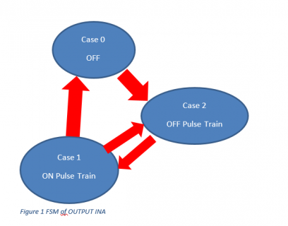
FSM Diagram Unipolar 27_04_2021.PNG
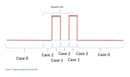
FSM Signal Graph Unipolar 27_04_2021.PNG

i am still confused how the FSM is handling the pulses because just counting up 1 2 3 makes more sense.
i think this has to do with the FSM that it has to start at resting position then do an action.

ok so now I have 10 pulses during the Pulse HIGH 50ms and Pulse LOW 50ms
i have tested the code twice and it works.

however once in the 5 or 10 pulse trains two pulses in the beginning of the pulse Train are HIGH, instead of
LOW HIGH LOW HIGH how come ?

how can I change the FSM to a else if Statement?

tomorrow ill do the second channel with an extra delay.

Code:
#define ENCODER_OPTIMIZE_INTERRUPTS
#include <SPI.h>
#include "Adafruit_MAX31855.h"
#include "HX8357_t3n.h"
#include <FlickerFreePrint.h>// library to draw w/o flicker
#include <math.h>
#include <stdio.h>
#include <elapsedMillis.h>
#include <ButtonEvents.h>
#include <ADC.h>
#include <Encoder.h>
#include <PID_v1.h>

//left side of the teensy4.1
const int INB_AntiClockwise       = 1;
const int INA_Clockwise           = 0;

const int PWM_DRV_TEC1_2_3        = 5;
const int PWM_DRV_PUMP            = 4;
const int PWM_EMAGNET             = 5;

unsigned int OFF_Time1 = 4000;                    //OFF Time
unsigned long repeatpulse = 10;
unsigned long PulseLOW = 50;
unsigned long PulseHIGH = 50;
elapsedMillis usec;// use only one variable for elapsedMillis/Micros
int Pulsecnt;
int state;
bool VNH5019 = LOW;   //it has not effect changing this from int to byte


////-----------------------------------------------Variables returned from analog inputs
int CSRAWTEC1_value;
int CSRAWTEC2_value;
int CSRAWTEC3_value;
int CSRAWEMAG_value;
//Current Factor x 3.3V ==16,7A
int Currentfactor1 = 5.06;
int Currentfactor2 = 5.06;
int Currentfactor3 = 5.06;
int Currentfactor4 = 5.06;

float TEC1Current;
float TEC2Current;
float TEC3Current;
float EMAGCurrent;


//-----------------------------------------------Default values for Sensors and PWM
float TempValue               = 0;               //encoder value to double
int PMPSpeed                  = 0;               //variable to be changed constrain and map
float  PMP_Liter_Min_Display  = 0;               //display value from the PUMP ==corresponds with max L/min Datasheet VPP655
int PMP_PWM                   = 0;               //Pump PWM
float EMAGNET                 = 0;               //Screen Value current is max 16.7A.
int EMAGNETPWM                = 0;               //PWM for Emagnet is 0.

//values cant go negative
unsigned long SampleTime = 0; // 1                 second


ButtonEvents myButton;  // Instantiate a Bounce object
ADC *IADC = new ADC(); //class ADC from the teensy read in Currents


void setup()
{
  Serial.begin(9600);

  //SPI CS pins for the MAX31855 need to be set high!

  //  pinMode(TFT_CS,     OUTPUT);            digitalWrite(TFT_CS, HIGH);
  pinMode(INB_AntiClockwise, OUTPUT);     digitalWrite(INB_AntiClockwise, LOW);
  pinMode(INA_Clockwise, OUTPUT);         digitalWrite(INA_Clockwise, LOW);
  //  pinMode(DIR_TEC_Cool, OUTPUT);
  pinMode(PWM_DRV_TEC1_2_3, OUTPUT);
  pinMode(PWM_DRV_PUMP, OUTPUT);
  pinMode(PWM_EMAGNET, OUTPUT);

  analogWriteResolution(12);
  analogWriteFrequency(PWM_DRV_TEC1_2_3, 20000);
  analogWriteFrequency(PWM_EMAGNET, 20000);

  state = 0;
  Pulsecnt = 0;
  usec = 0;

}

void loop()
{

  switch (state)
  {
    case 0:
      if (usec >= OFF_Time1)
      {
        VNH5019 = HIGH;
        digitalWrite(INA_Clockwise, LOW); digitalWrite(INB_AntiClockwise, LOW);  //doesnt matter high or low both need to be HIGH or LOW.
        //required for Timedelay max
        usec = 0;
        Pulsecnt = 0;
        state = 1;
        Serial.println("begin state 0");
      }
      break;

 case 1:
      if (usec >= PulseLOW)
      {
        digitalWrite(INB_AntiClockwise, LOW); digitalWrite(INA_Clockwise, LOW);
        Pulsecnt = Pulsecnt + 1;
        //reset the elapsedMicros
        state = 2;
        Serial.println("begin state 1");
        usec = 0;
      }
      break;

case 2:
      if (usec >= PulseHIGH) //Case 2 //50ms//50000usec
      {
        if (Pulsecnt < repeatpulse) //repeat pulses 50ms
        {
          digitalWrite(INA_Clockwise, HIGH);
          analogWrite(PWM_DRV_TEC1_2_3, 2500); //2700 is the limit //thermal
          Serial.println("begin state 2");
          usec = 0;
          state = 1;
        }
        else
        {
          digitalWrite(INA_Clockwise, LOW);
          state = 0;
        }

      }
      break;
  }
}
 
Last edited:
hi,

for using two signals i splitted up the FSM in two FSM which respresent their own channel.
the first channel 0 is Clockwise as can been seen in post 36.

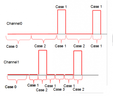
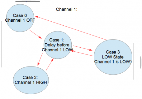
the following attached signal Channel 1 represents during the OFF State of Channel 0 = Channel 1, but with two extra states States 1 and State 3: 1 = is the delay which is repeated and state 3 is the Channel 0 which is on in the other FSM.

I have attached both drawings into one, showing the FSM of the channel 1 and signal Graph for both for understanding.
State Channel 0and 1.PNG
diagram FSM Channel1.PNG

problem:
i have problems counting up the case 1 2ms delay how do i count the states of case 1 for channel 1

the following code is not complete! so do not compile.
my question is where in the FSM do I place the count of the delays
i think the FSM is correct for the Channel 1 but i dont understand when to count the delays. because this decides when and where the states are switched from state 3 to state 1 and to state 0.

its marked in red where i have questions its ( further down in the code).

Code:
#define ENCODER_OPTIMIZE_INTERRUPTS
#include <SPI.h>
#include "Adafruit_MAX31855.h"
#include "HX8357_t3n.h"
#include <FlickerFreePrint.h>// library to draw w/o flicker
#include <math.h>
#include <stdio.h>
#include <elapsedMillis.h>
#include <ButtonEvents.h>
#include <ADC.h>
#include <Encoder.h>
#include <PID_v1.h>

//left side of the teensy4.1
const int INB_AntiClockwise       = 1;
const int INA_Clockwise           = 0;

const int PWM_DRV_TEC1_2_3        = 5;
const int PWM_DRV_PUMP            = 4;
const int PWM_EMAGNET             = 5;

unsigned int OFF_Time1 = 4000;                    //OFF Time
unsigned long repeatpulse = 10;
unsigned long PulseLOW = 50;
unsigned long PulseHIGH = 50;
elapsedMillis usec;// use only one variable for elapsedMillis/Micros
int Pulsecnt;
int State_CH0;//INA Clockwise


int State_CH1;//INB Anti
unsigned long repeatpulseAnti = 10;
unsigned long Delaybetween = 2;
unsigned long DelayAfter = 2;
unsigned long PulseAnti = (PulseLOW - (Delaybetween + DelayAfter));
int PulsecntAnti;
bool VNH5019 = LOW;   //it has not effect changing this from int to byte

//-----------------------------------------------Default values for Sensors and PWM
float TempValue               = 0;               //encoder value to double
int PMPSpeed                  = 0;               //variable to be changed constrain and map
float  PMP_Liter_Min_Display  = 0;               //display value from the PUMP ==corresponds with max L/min Datasheet VPP655
int PMP_PWM                   = 0;               //Pump PWM
float EMAGNET                 = 0;               //Screen Value current is max 16.7A.
int EMAGNETPWM                = 0;               //PWM for Emagnet is 0.

//values cant go negative
unsigned long SampleTime = 0; // 1                 second


ButtonEvents myButton;  // Instantiate a Bounce object
ADC *IADC = new ADC(); //class ADC from the teensy read in Currents


void setup()
{
  Serial.begin(9600);

  //SPI CS pins for the MAX31855 need to be set high!

  //  pinMode(TFT_CS,     OUTPUT);            digitalWrite(TFT_CS, HIGH);
  pinMode(INB_AntiClockwise, OUTPUT);     digitalWrite(INB_AntiClockwise, LOW);
  pinMode(INA_Clockwise, OUTPUT);         digitalWrite(INA_Clockwise, LOW);
  //  pinMode(DIR_TEC_Cool, OUTPUT);
  pinMode(PWM_DRV_TEC1_2_3, OUTPUT);
  pinMode(PWM_DRV_PUMP, OUTPUT);
  pinMode(PWM_EMAGNET, OUTPUT);

  analogWriteResolution(12);
  analogWriteFrequency(PWM_DRV_TEC1_2_3, 20000);
  analogWriteFrequency(PWM_EMAGNET, 20000);

  State_CH0 = 0;
  Pulsecnt = 0;
  usec = 0;

  State_CH1 = 0;
  PulsecntAnti =;


}

void loop()
{

  switch (State_CH0)
  {
    case 0:
      if (usec >= OFF_Time1)
      {
        VNH5019 = HIGH;
        digitalWrite(INA_Clockwise, LOW); digitalWrite(INB_AntiClockwise, LOW);  //doesnt matter high or low both need to be HIGH or LOW.
        //required for Timedelay max
        usec = 0;
        Pulsecnt = 0;
        State_CH0 = 1;
        Serial.println("begin State_CH1 0");
      }
      break;

    case 1:
      if (usec >= PulseLOW)
      {
        digitalWrite(INB_AntiClockwise, LOW); digitalWrite(INA_Clockwise, LOW);
        Pulsecnt = Pulsecnt + 1;
        //reset the elapsedMicros
        State_CH0 = 2;
        Serial.println("begin State_CH1 1");
        usec = 0;
      }
      break;

    case 2:
      if (usec >= PulseHIGH) //Case 2 //50ms//50000usec
      {
        if (Pulsecnt < repeatpulse) //repeat pulses 50ms
        {
          digitalWrite(INA_Clockwise, HIGH);
          analogWrite(PWM_DRV_TEC1_2_3, 2500); //2700 is the limit //thermal
          Serial.println("begin State_CH1 2");
          usec = 0;
          State_CH0 = 1;
        }
        else
        {
          digitalWrite(INA_Clockwise, LOW);
          State_CH0 = 0;
        }

      }
      break;
  }


  /*

    int State_CH1;//INB Anti
    unsigned long repeatpulseAnti = 10;
    unsigned long Delaybetween = 2;
    unsigned long DelayAfter = 2;
    unsigned long PulseAnti = (PulseLOW - (Delaybetween + DelayAfter));
    int PulsecntAnti;
    bool VNH5019 = LOW;

  */
///------------------------------------------------------------------------------------other OUTPUT Channel 1
  switch (State_CH1) //INB_AntiClockwise
  {
    case 0:
      if (usec >= OFF_Time1)
      {
        VNH5019 = HIGH;
        digitalWrite(INA_Clockwise, LOW); digitalWrite(INB_AntiClockwise, LOW);  //doesnt matter high or low both need to be HIGH or LOW.
        //required for Timedelay max
        usec = 0;
        PulsecntAnti = 0;
        State_CH1 = 1;
        Serial.println("begin State_CH1 0");
      }
      break;
    case 1:
      if (usec >= Delaybetween)
      {
        PulsecntAnti=PulsecntAnti+1;
        digitalWrite(INB_AntiClockwise, LOW);
        usec = 0;
        State_CH1 = 2;
///
      }
      break;
    case 2:
      if (usec >= PulseAnti) //pulse anti is shorter then the Channel 0! 2ms + 46ms +2ms.
      {
        
       //set the Pulse HIGH
        usec = 0; //reset the delay
        State_CH1 = 1;//repeat the delay state before and after the Case 2
        digitalWrite(INB_AntiClockwise, HIGH);
      }
     if(PulsecntAnti==2)[COLOR="#FF0000"]// is this correct, if PulsecntAnti becomes 2 then move tot state 3? can i do this?[/COLOR]
    {
     State_CH2=3; //Channel 0 is now high
     usec=0;
     PulsecntAnti=0; //reset count of delays
     }

   }
   break;
   case 3:
      if(usec>PulseHIGH)
      {
       digitalWrite(INB_AntiClockwise, LOW);
       usec=0;
       state=1; //back to state 1 delay
       Pulsecnt =Pulsecnt+1;
      }
       if(Pulsecnt==10) //counts the pulses from the previous FSM Channel 0
       {
       usec=0;
[COLOR="#FF0000"][COLOR="#FF0000"]       state=0; //back to state 0?[/COLOR][/COLOR]
    

       }


}

the code where i have doubts are marked in red. am i missing something?
 
Last edited:
hi

I think i almost have the code fixed for 1000 mseconds OFF,
then 52ms x 10 pulses on and off with a 2ms shift between two channels.

previous post shows the graphs and the way i understood it from pauls drawings.
programming for me was not that straightforward.

I accidently stumbled over a state, which i thought I didnt need. and put it to Zero.
i tried removing it but that puts my pulses for CH1 LOW. so i somehow need it, but in which constellation of programming i dont know.

this is the snippet of code which does something miraculously for me.

Code:
 case 3:
      if (usec_CH1 >=0)// be HIGH till 52ms and go low.
      {

        usec_CH1 = 0;
        digitalWrite(INB_AntiClockwise, HIGH);
        State_CH1 = 4;


      }
      break;


could someone hook up 2 pins 0,1 and run the following code?
and tell me where my fault is?
especially for if you change the pulses HIGH and LOW state to 500ms what would happen then?
and does the drawing i made for the FSM, match the code?
I created for each OUTPUT a FSM so that i can see what the signal does.

many thanks.

this code has been tested a few times.

Code:
#define ENCODER_OPTIMIZE_INTERRUPTS
#include <SPI.h>
#include "Adafruit_MAX31855.h"
#include "HX8357_t3n.h"
#include <FlickerFreePrint.h>// library to draw w/o flicker
#include <math.h>
#include <stdio.h>
#include <elapsedMillis.h>
#include <ButtonEvents.h>
#include <ADC.h>
#include <Encoder.h>
#include <PID_v1.h>

//left side of the teensy4.1
const int INB_AntiClockwise       = 1;
const int INA_Clockwise           = 0;

const int PWM_DRV_TEC1_2_3        = 5;
const int PWM_DRV_PUMP            = 4;
const int PWM_EMAGNET             = 5;

unsigned int OFF_Time1 = 1000;                    //OFF Time

elapsedMillis usec_CH0;// use only one variable for elapsedMillis/Micros
elapsedMillis usec_CH1;// use only one variable for elapsedMillis/Micros
int Pulsecnt;//pulses for CH0
int State_CH0;//INA Clockwise
int State_CH1;//INB Anti
int PulsecntCH1;// pulses for CH1
bool VNH5019 = LOW;   //it has not effect changing this from int to byte

//-----------------------------------------------Default values for Sensors and PWM
float TempValue               = 0;               //encoder value to double
int PMPSpeed                  = 0;               //variable to be changed constrain and map
float  PMP_Liter_Min_Display  = 0;               //display value from the PUMP ==corresponds with max L/min Datasheet VPP655
int PMP_PWM                   = 0;               //Pump PWM
float EMAGNET                 = 0;               //Screen Value current is max 16.7A.
int EMAGNETPWM                = 0;               //PWM for Emagnet is 0.

//values cant go negative
unsigned long SampleTime = 0; // 1                 second


ButtonEvents myButton;  // Instantiate a Bounce object
ADC *IADC = new ADC(); //class ADC from the teensy read in Currents


void setup()
{
  Serial.begin(9600);

  //SPI CS pins for the MAX31855 need to be set high!

  //  pinMode(TFT_CS,     OUTPUT);            digitalWrite(TFT_CS, HIGH);
  pinMode(INB_AntiClockwise, OUTPUT);     digitalWrite(INB_AntiClockwise, LOW);
  pinMode(INA_Clockwise, OUTPUT);         digitalWrite(INA_Clockwise, LOW);
  //  pinMode(DIR_TEC_Cool, OUTPUT);
  pinMode(PWM_DRV_TEC1_2_3, OUTPUT);
  pinMode(PWM_DRV_PUMP, OUTPUT);
  pinMode(PWM_EMAGNET, OUTPUT);

  analogWriteResolution(12);
  analogWriteFrequency(PWM_DRV_TEC1_2_3, 20000);
  analogWriteFrequency(PWM_EMAGNET, 20000);


//channel OUTPUT 0 FSM 1
  State_CH0       = 0;
  Pulsecnt        = 0;
  usec_CH0        = 0;

//channel OUTPUT 1 FSM 2
  usec_CH1        = 0;
  State_CH1       = 0;
  PulsecntCH1     = 0;


}

void loop()
{
//FSM 1
  switch (State_CH0) //INB_AntiClockwise //channel 2 Oscilloscope 52ms pulse LOW and HIGH
  {

    case 0:
      if (usec_CH0 >= (OFF_Time1))// off time for both FSM are the same!
      {
        VNH5019 = HIGH;
        digitalWrite(INA_Clockwise, HIGH);  //doesnt matter high or low both need to be HIGH or LOW.
        //required for Timedelay max
        usec_CH0 = 0;
        Pulsecnt = 0;
        State_CH0 = 1;//move to state 1
        Serial.println("begin State_CH0 0");
      }

      break;
    case 1:
      if (usec_CH0 >= 50) //below for 50ms
      {
        Pulsecnt=Pulsecnt+1;//start counting on LOW Pulse
        Serial.println("begin State_CH1 State 1 LOW");
        digitalWrite(INA_Clockwise, LOW);
        usec_CH0 = 0;
        State_CH0 = 2;
      }
      break;
    case 2:
      if (usec_CH0 >= 2) //be low for 2ms
      {

        digitalWrite(INA_Clockwise, LOW);//add a 2ms delay
        //set the Pulse HIGH
        usec_CH0 = 0; //reset the delay
        State_CH0 = 3;//repeat the delay state before and after the Case 2

      }
      break;
    case 3:
      if (usec_CH0 >= 50)// be high for 50ms
      {
        usec_CH0 = 0;
        digitalWrite(INA_Clockwise, HIGH);
        State_CH0 = 4;
      }
      break;

    case 4:// be high + 2ms
      if (usec_CH0 >= 2)
      { if (Pulsecnt <= 10)//if number of pulses is not met go bck tot state 1
        {
          usec_CH0 = 0;
          digitalWrite(INA_Clockwise, HIGH);
          State_CH0 = 1;
        }
        else
        {
          digitalWrite(INA_Clockwise, HIGH);
          usec_CH0 = 0;
          State_CH0 = 0;
          Pulsecnt=0;
        }
      }
      break;


  }


  //FSM 2
  switch (State_CH1) //INB_AntiClockwise //channel 1 Oscilloscope
  {

    case 0:
      if (usec_CH1 >= (OFF_Time1))// off time for both FSM are the same!
      {
        VNH5019 = HIGH;
        digitalWrite(INB_AntiClockwise, LOW);  
        
        usec_CH1 = 0;
        PulsecntCH1 = 0;
        State_CH1 = 1;
       

      }
      break;
    case 1:
      if (usec_CH1 >= 50) //pulse low

{
        Serial.println("begin State_CH1 State 1 LOW");
        digitalWrite(INB_AntiClockwise, LOW);
        usec_CH1 = 0;
        State_CH1 = 2;
      }
      break;
    case 2:
      if (usec_CH1 >=2) //pulse low for 52ms
      {
        PulsecntCH1 = PulsecntCH1 + 1;
        digitalWrite(INB_AntiClockwise, LOW);
        //set the Pulse HIGH
        usec_CH1 = 0; //reset the delay
        State_CH1 = 3;//repeat the delay state before and after the Case 2
      }
      break;
    case 3:
      if (usec_CH1 >=0)///somehow this works, i changed it to Zero, i am not seing the problem or logic error.
      {
        usec_CH1 = 0;
        digitalWrite(INB_AntiClockwise, HIGH);
        State_CH1 = 4;
      }
      break;

    case 4:
      if (usec_CH1 >= 52)//pulse high
      {
        if (PulsecntCH1 < 10)
        {
          usec_CH1 = 0;// elapsedmillis =0;
          digitalWrite(INB_AntiClockwise, LOW);
          State_CH1 = 1;//back to State 1; repeat the states.

        }
        else
        { usec_CH1 = 0; // elapsedmillis =0;
          State_CH1 = 0;//go back to startf
          PulsecntCH1 = 0;//reset number of pulses if pulses are reached
           digitalWrite(INB_AntiClockwise, LOW);
        }

      }
      break;
  }


}
 
Status
Not open for further replies.
Back
Top