Teensy 4.1 with array of TDM mictophones

Status
Not open for further replies.

FelixWZ

Member
Hello guys,

I am struggling to wire up my TDM/I2S array microphones to the Teensy 4.1 board.

Issue N-1: Two I2S stereo microphones


I'm using Infineon IM69D130 Microphone Shield2Go
Datasheet link

Connected by the next way:
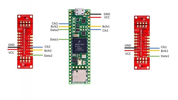
Teensy with 2 shields wiring.jpg
While im running next configuration code

#include <Audio.h>
#include <Wire.h>
#include <SPI.h>
#include <SD.h>
#include <SerialFlash.h>


// GUItool: begin automatically generated code
AudioInputI2S i2s1; //xy=275,91
AudioInputI2S i2s2; //xy=276.00000381469727,151.00000190734863
// GUItool: end automatically generated code

only I2S1 generating Clock and Wclock, the I2S2 port not doing it. Do I connect it to the right pins?

-----------------------------------------------------------------------------------------------------------------------------------

Issue N-2: 8 TDM format microphones

I'm using the same Infineon IM69D130 Microphone Shield2Go that can be used in TDM format, next pic taken from the Shield2Go Datasheet Page.5 Datasheet link
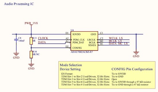
TDM format.JPG

I need an advice how to wire up four of this shield to the Teensy 4.1 and some example of code to start working with this configuration.
 
only I2S1 generating Clock and Wclock, the I2S2 port not doing it. Do I connect it to the right pins?

Those connections appear to be correct.


I need an advice how to wire up four of this shield to the Teensy 4.1

To connect 4 of those boards, I would first try using AudioOutputI2SOct, which is i2s_oct in the design tool.

Then for wiring, I would their clocks to pins 21 and 23 (so each of those pins on Teensy gets 4 wires). Teensy transmits the clocks, so it's ok to send the same clocks to 4 different boards. Each board's data needs a dedicated pin. Wire them to Teensy pins 7, 32, 9, 6.

Keep the wiring neat & tidy. Having the GND wire physically close to the clock wires helps reduce high frequency noise problems.

I would probably not mess with TDM. While TDM should be theoretically possible by soldering different resistors onto those Shield2Go boards, troubleshooting TDM (assuming it doesn't go as planned) is likely to end up being a nightmare. You're (probably) much better off just leaving those Shield2Go boards in their default configuration and use 4 data wires rather than trying to combine all the data as TDM on a signal data line.

When I2S doesn't work, troubleshooting is easier since each Shield2Go has a dedicated data path to Teensy. Troubleshooting involves using a scope or logic analyzer (or multimeter which can measure high frequencies - most cheap handheld ones can't) to check whether the Shield2Go is receiving both clocks. If it is getting clocks, is it then transmitting data to Teensy. Much simpler to debug when each Shield2Go has its own data wire.
 
only I2S1 generating Clock and Wclock, the I2S2 port not doing it. Do I connect it to the right pins?

You're not getting clocks on pins 3 & 4 because you have 2 copies of AudioInputI2S.

Code:
// GUItool: begin automatically generated code
AudioInputI2S i2s1; //xy=275,91
AudioInputI2S i2s2; //xy=276.00000381469727,151.00000190734863
// GUItool: end automatically generated code

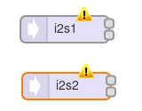
When you created this in the design tool, it should have shown you these little yellow error icons.

screenshot.png

If you click on each, you'll see the documentation panel shows they are both using the same pins (21, 23, 8, 20). That can't possibly work because both are trying to use the same physical port which uses the same pins. The design tool "knows" which resources each input & output uses. When you put 2 or more into your design which conflict for physical hardware resources, those error icons show you that your design will not work when actually run on Teensy.

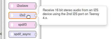
To make this work, you need to use this other I2S input which uses the 2nd port on pins 4, 33, 5, 3.

screenshot2.png
 
Status
Not open for further replies.
Back
Top