Hi,
First of all, thank you for all your valuable contributions in the Forum. They helped me a lot to finalize the code for my project without beeing in need to ask any questions.
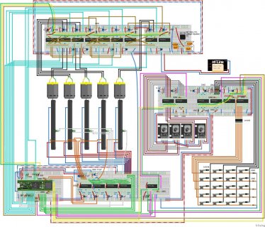
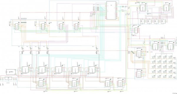
I want to build a MIDI Controller with approx. 15 Motorfaders, 4 Encoders and 200+ Buttons. All similar projects with that size had quite difficult code using more then the "basic" commants, which made it hard for me to understand them.
However, I managed to create a working code from extending the basics I did understand instead of copying another project.
Before I start designing the PCB layout, it would be awsome if any of you who is interested and got some time could look over and tell me if there is something that will not work out and must be changed.
I also got some specific questions:
Some things I am aware of:
Usually port expanders like MCP23S17 and interrupts are used for encoder. However, shift registers did work fine for me.
Often short delays are used when reading multiplexed analog signals. However, it did work fine without.
I found the ResponsiveAnalogRead Library after I finished my code. Maybe I am going to try it out. However, as it already works as is, I don't see much reason for it.
Thank you in advance.
PS: I was not able to upload high resolution attachements here, therefore I also uploaded them there:
https://www.docdroid.net/UrdCGBx/midi-controller-breadboard-pdf
https://www.docdroid.net/M3qSU2D/midi-controller-plan-pdf
First of all, thank you for all your valuable contributions in the Forum. They helped me a lot to finalize the code for my project without beeing in need to ask any questions.
I want to build a MIDI Controller with approx. 15 Motorfaders, 4 Encoders and 200+ Buttons. All similar projects with that size had quite difficult code using more then the "basic" commants, which made it hard for me to understand them.
However, I managed to create a working code from extending the basics I did understand instead of copying another project.
Before I start designing the PCB layout, it would be awsome if any of you who is interested and got some time could look over and tell me if there is something that will not work out and must be changed.
I also got some specific questions:
- When all the faders are moved at the same time by the PC software (due to a fader page change), sometimes some faders move a little slower than others. Further, I have the feeling that they move a bit slower compared to moving a single fader only (see video: https://streamable.com/k7kcmf). One reason might be, that currently I have very old used faders and their motors are propably worn out. However, I also think it could be a power supply issue and I don't want to run into problems on the final controller with 15 motor faders. Any tips here? I routed the power supply line twice to the breadborard with the faders H-Briges already.
- I used decoupling capacitors on the voltage supply pins of all chips. Do I need to do the same on other pins that are connected to the voltage supply? Example: SRCLR* Pins of the 74HC595 shift registers.
- I use capacitors to smooth the analog signals from the faders. However, as they are on a multiplexer, do I need to add a resistor like R2 on page 12 and 13 in the following document to avoid something like a short circuit?
Or won't this happen anyhow? In no basic button-tutorial there is a resitor between VCC and a pressed button. Usually only pulldowns are used there...
For me switching between faders would be similar to pressing a button and therefore I do not think it is required.
https://my.eng.utah.edu/~cs5780/debouncing.pdf - I am using a Teensy 3.6. Therefore, I can use the native touchRead function. However, I also found the FastTouch Library from adrianfreed and it is much faster then the normal touchRead. As the FastTouch Version switches the Teensy's pins state from LOW to HIGH and back all the time, will this do any harm to the teensy or the person touching the fader over time? Are there any other disadvantages?
- Is there any way to remove the diodes from the button matrix without having a "ghosting" effect when pressing multiple buttons?
Some things I am aware of:
Usually port expanders like MCP23S17 and interrupts are used for encoder. However, shift registers did work fine for me.
Often short delays are used when reading multiplexed analog signals. However, it did work fine without.
I found the ResponsiveAnalogRead Library after I finished my code. Maybe I am going to try it out. However, as it already works as is, I don't see much reason for it.
Thank you in advance.
Code:
/* Include Libraries */
//#include <FastTouch.h>
#include <SPI.h>

/* Define pins */
const int touchReadPin1 = 0;
const int touchReadPin2 = 1;
const int faderValuePin1 = A16;
const int faderValuePin2 = A15;
const int multiplexPinS0 = 24;
const int multiplexPinS1 = 25;
const int multiplexPinS2 = 26;
const int buttonRegisterLatchPin = 27;
const int encoderRegisterLatchPin = 28;
const int motorRegisterLatchPin = 15;
const int pwmPin[15] = {2, 5, 6, 7, 8, 9, 10, 14, 20, 21, 22, 23, 36, 37, 38};

/* Define variables for loops */
int a = 0;
int b = 0;
int c = 0;
int d = 0;
int x = 0;
int y = 0;
int z = 0;

/* Define variables for buttons and encoders. Large variables are filled in the setup section. Encoders have integrated pull-ups. For buttons bull-donws are used. Encoders are connected to input shift registers, as this did work. No port expanders required.
 * Buttons are connected to a matrix of output and input shift registers. For each scan-cycle only one pin of all output shift registers is set high. Using INPUT_PULLUP did not work proper. Diodes are used in the matrix. */
int buttonStateCh2[128];
int buttonStateCh3[128];
int lastButtonStateCh2[128];
int lastButtonStateCh3[128];
int encoderButtonState[4]                       = {HIGH, HIGH, HIGH, HIGH};
int lastEncoderButtonState[4]                   = {HIGH, HIGH, HIGH, HIGH};
int encoderRotationState[8]                     = {HIGH, HIGH, HIGH, HIGH, HIGH, HIGH, HIGH, HIGH};
int lastEncoderRotationState[8]                 = {HIGH, HIGH, HIGH, HIGH, HIGH, HIGH, HIGH, HIGH};
int encoderRotationDirection[8]                 = {HIGH, HIGH, HIGH, HIGH, HIGH, HIGH, HIGH, HIGH};
byte buttonRegister1Out[16]                     = {B00000000, B00000000, B00000000, B00000000, B00000000, B00000000, B00000000, B00000000, B10000000, B01000000, B00100000, B00010000, B00001000, B00000100, B00000010, B00000001};
byte buttonRegister2Out[16]                     = {B10000000, B01000000, B00100000, B00010000, B00001000, B00000100, B00000010, B00000001, B00000000, B00000000, B00000000, B00000000, B00000000, B00000000, B00000000, B00000000};
byte buttonRegisterIn[2];
byte encoderRegisterIn[2]                       = {B11111111, B11111111};
unsigned long lastButtonChangeTimeCh2[128];
unsigned long lastButtonChangeTimeCh3[128];
unsigned long lastEncoderButtonChangeTime[4]    = {0, 0, 0, 0};
const int debounceTime = 50;

/* Define variables for faders and motors. Motors are driven by H-bridges. The direction pins of the H-bridges are set by output shift registers. The speed is controlled via PWM. */
int faderValue[15];
int smoothFaderValue[15];
int mappedFaderValue[15];
int lastMappedFaderValue[15];
int faderDistance[15];
byte pcFaderNumber;
int pcFaderValue[15];
int touchIntensity[15];
int multiplexControlBit0 = 0;
int multiplexControlBit1 = 0;
int multiplexControlBit2 = 0;
unsigned long startTimeTouch[15]  = {0, 0, 0, 0, 0, 0, 0, 0, 0, 0, 0, 0, 0, 0, 0};
const int maxUntouchedTime        = 500;
unsigned long startTimeFade[15]   = {0, 0, 0, 0, 0, 0, 0, 0, 0, 0, 0, 0, 0, 0, 0};
const int maxFadeTime             = 500;
int touchCheckTime[15]            = {0, 0, 0, 0, 0, 0, 0, 0, 0, 0, 0, 0, 0, 0, 0};
const int touchCheckInterval      = 50;
boolean fadeActive[15]            = {false, false, false, false, false, false, false, false, false, false, false, false, false, false, false};
byte motorRegister[4]             = {B00000000, B00000000, B00000000, B00000000};
int pwmMode[15]                   = {0, 0, 0, 0, 0, 0, 0, 0, 0, 0, 0, 0, 0, 0, 0};

/* Define variables for PWM speeds. They are different in between the motors, because some of my motors are crap. */
const int pwmFull           = 2048;
const int pwmUpFast[15]     = {1850, 1900, 2000, 1850, 1900, 1900, 1900, 1900, 1900, 1900, 1900, 1900, 1900, 1900, 1900};
const int pwmUpMedium[15]   = {1700, 1750, 1850, 1700, 1750, 1750, 1750, 1750, 1750, 1750, 1750, 1750, 1750, 1750, 1750};
const int pwmUpSlow[15]     = {1625, 1650, 1675, 1625, 1650, 1650, 1650, 1650, 1650, 1650, 1650, 1650, 1650, 1650, 1650};
const int pwmDownFast[15]   = {1900, 2048, 2048, 1900, 1900, 1900, 1900, 1900, 1900, 2000, 1900, 1900, 1900, 1900, 1900};
const int pwmDownMedium[15] = {1750, 2000, 2000, 1750, 1750, 1750, 1750, 1750, 1750, 1900, 1750, 1750, 1750, 1750, 1750};
const int pwmDownSlow[15]   = {1650, 1975, 1975, 1650, 1650, 1650, 1650, 1650, 1650, 1800, 1650, 1650, 1650, 1650, 1650};
const int pwmOff = 0;

/* Define variables for benchmark. */
int loops = 0;
unsigned long actualRunTime = 0;
unsigned long lastRunTime = 0;

void setup() {

/* Define output pins. */
  pinMode(motorRegisterLatchPin, OUTPUT);
  pinMode(buttonRegisterLatchPin, OUTPUT);
  pinMode(encoderRegisterLatchPin, OUTPUT);
  pinMode(multiplexPinS0, OUTPUT);
  pinMode(multiplexPinS1, OUTPUT);
  pinMode(multiplexPinS2, OUTPUT);
  for ( x = 0; x < 15; x++ ) {
    pinMode(pwmPin[x], OUTPUT);
  }

/* Define PWM frequency and resolution. */
  analogWriteFrequency(2, 29296.875);
  analogWriteFrequency(5, 29296.875);
  analogWriteResolution(11);

/* Stabilze after boot. */
  delay(1000);

/* Initial read of fader positions. Faders are connected to two multiplexers. 1020 is max, as in the program a low pass filter is used for smoothing. */
  for ( x = 0; x < 8; x++ ) {
    multiplexControlBit0 = bitRead(x, 0);
    multiplexControlBit1 = bitRead(x, 1);
    multiplexControlBit2 = bitRead(x, 2);
    digitalWrite(multiplexPinS0, multiplexControlBit0);
    digitalWrite(multiplexPinS1, multiplexControlBit1);
    digitalWrite(multiplexPinS2, multiplexControlBit2);
    faderValue[x] = analogRead(faderValuePin1);
    if (faderValue[x] > 1020) {
      faderValue[x] = 1020;
    }
    smoothFaderValue[x] = faderValue[x];
    mappedFaderValue[x] = map(smoothFaderValue[x],0,1020,0,127);
    lastMappedFaderValue[x] = mappedFaderValue[x];
  }
  for ( x = 0; x < 7; x++ ) {
    multiplexControlBit0 = bitRead(x, 0);
    multiplexControlBit1 = bitRead(x, 1);
    multiplexControlBit2 = bitRead(x, 2);
    digitalWrite(multiplexPinS0, multiplexControlBit0);
    digitalWrite(multiplexPinS1, multiplexControlBit1);
    digitalWrite(multiplexPinS2, multiplexControlBit2);
    faderValue[x+8] = analogRead(faderValuePin2);
    if (faderValue[x+8] > 1020) {
      faderValue[x+8] = 1020;
    }
    smoothFaderValue[x+8] = faderValue[x+8];
    mappedFaderValue[x+8] = map(smoothFaderValue[x+8],0,1020,0,127);
    lastMappedFaderValue[x+8] = mappedFaderValue[x+8];
  }

/* Filling large variables. */
for (d = 0; d < 128; d++) {
  buttonStateCh3[d] = 0;
  buttonStateCh3[d] = 0;
  lastButtonStateCh2[d] = 0;
  lastButtonStateCh3[d] = 0;
  lastButtonChangeTimeCh2[d] = 0;
  lastButtonChangeTimeCh3[d] = 0;
}

/* Initial fill the output registers that drive motors. Same SPI speed and mode is used for all registers. Therefore, SPI.beginTransaction is only used once without ending it anywhere. */
  SPI.begin();
  SPI.beginTransaction(SPISettings(15000000, MSBFIRST, SPI_MODE0));
  digitalWrite(motorRegisterLatchPin, LOW);
  SPI.transfer(motorRegister[0]);
  SPI.transfer(motorRegister[1]);
  SPI.transfer(motorRegister[2]);
  SPI.transfer(motorRegister[3]);
  digitalWrite(motorRegisterLatchPin, HIGH);
//  SPI.endTransaction();
}

void loop() {

/* Reading the buttons.
 * The same latch pin is used for input and output registers: LOW -> teensy can write to output registers, HIGH -> store written data on ouput registers, LOW -> input registers can read data on pins, HIGH -> input register is read by teensy.
 * Output registers are not changed on the second change from LOW to HIGH, as no new data had been sent. */
  d = 0;
  for (a = 0; a < 8 ; a++) {
    digitalWrite(buttonRegisterLatchPin, LOW);
    SPI.transfer(buttonRegister1Out[a]);
    SPI.transfer(buttonRegister2Out[a]);
    digitalWrite(buttonRegisterLatchPin, HIGH);
    digitalWrite(buttonRegisterLatchPin, LOW);
    digitalWrite(buttonRegisterLatchPin, HIGH);
    for ( b = 0; b < 2; b++ ) {
      buttonRegisterIn[b] = SPI.transfer(0);
      for ( c = 0 ; c < 8; c++ ) {
        buttonStateCh2[d] = bitRead(buttonRegisterIn[b], c);
          if (buttonStateCh2[d] == HIGH && lastButtonStateCh2[d] == LOW) {
            if ((millis() - lastButtonChangeTimeCh2[d]) > debounceTime) {
              usbMIDI.sendNoteOn(d, 127, 2);
              lastButtonChangeTimeCh2[d] = millis();
              lastButtonStateCh2[d] = buttonStateCh2[d];
            }
          }
          if (buttonStateCh2[d] == LOW && lastButtonStateCh2[d] == HIGH) {
            if ((millis() - lastButtonChangeTimeCh2[d]) > debounceTime) {
              usbMIDI.sendNoteOff(d, 0, 2);
              lastButtonChangeTimeCh2[d] = millis();
              lastButtonStateCh2[d] = buttonStateCh2[d];
            }
          }
        d++;
      }
    }
  }
  d = 0;
  for (a = 8; a < 16 ; a++) {
    digitalWrite(buttonRegisterLatchPin, LOW);
    SPI.transfer(buttonRegister1Out[a]);
    SPI.transfer(buttonRegister2Out[a]);
    digitalWrite(buttonRegisterLatchPin, HIGH);
    digitalWrite(buttonRegisterLatchPin, LOW);
    digitalWrite(buttonRegisterLatchPin, HIGH);
    for ( b = 0; b < 2; b++ ) {
      buttonRegisterIn[b] = SPI.transfer(0);
      for ( c = 0 ; c < 8; c++ ) {
        buttonStateCh3[d] = bitRead(buttonRegisterIn[b], c);
          if (buttonStateCh3[d] == HIGH && lastButtonStateCh3[d] == LOW) {
            if ((millis() - lastButtonChangeTimeCh3[d]) > debounceTime) {
              usbMIDI.sendNoteOn(d, 127, 3);
              lastButtonChangeTimeCh3[d] = millis();
              lastButtonStateCh3[d] = buttonStateCh3[d];
            }
          }
          if (buttonStateCh3[d] == LOW && lastButtonStateCh3[d] == HIGH) {
            if ((millis() - lastButtonChangeTimeCh3[d]) > debounceTime) {
              usbMIDI.sendNoteOff(d, 0, 3);
              lastButtonChangeTimeCh3[d] = millis();
              lastButtonStateCh3[d] = buttonStateCh3[d];
            }
          }
        d++;
      }
    }
  }

/* Reading the encoders. They are connected to two input shift registers. */
  digitalWrite(encoderRegisterLatchPin, HIGH);
  encoderRegisterIn[0] = SPI.transfer(0);
  encoderRegisterIn[1] = SPI.transfer(0);
  digitalWrite(encoderRegisterLatchPin, LOW);
  for ( d = 0 ; d < 4; d++ ) {
    encoderButtonState[d] = bitRead(encoderRegisterIn[0], d);
      if (encoderButtonState[d] == LOW && lastEncoderButtonState[d] == HIGH) {
        if ((millis() - lastEncoderButtonChangeTime[d]) > debounceTime) {
          usbMIDI.sendNoteOn(d, 127, 4);
          lastEncoderButtonChangeTime[d] = millis();
          lastEncoderButtonState[d] = encoderButtonState[d];
        }
      }
      if (encoderButtonState[d] == HIGH && lastEncoderButtonState[d] == LOW) {
        if ((millis() - lastEncoderButtonChangeTime[d]) > debounceTime) {
          usbMIDI.sendNoteOff(d, 0, 4);
          lastEncoderButtonChangeTime[d] = millis();
          lastEncoderButtonState[d] = encoderButtonState[d];
        }
      }
  }
  c = 0;
  for ( d = 0 ; d < 4; d++ ) {
    encoderRotationState[c] = bitRead(encoderRegisterIn[1], c);
    encoderRotationDirection[c+1] = bitRead(encoderRegisterIn[1], c+1);
      if (encoderRotationState[c] == LOW && lastEncoderRotationState[c] == HIGH) {
        if (encoderRotationDirection[c+1] == LOW) {
          usbMIDI.sendControlChange(d, 1, 5);
        }
        else {
          usbMIDI.sendControlChange(d, 0, 5);
        }
      }
    lastEncoderRotationState[c] = encoderRotationState[c];
    c = c + 2;
  }

/* Checking for MIDI-IN data on channel 1. */
  if (usbMIDI.read(1) != 0) {
    pcFaderNumber = usbMIDI.getData1();
    for ( x = 0; x < 15; x++ ) {
      if (pcFaderNumber == x) {
        pcFaderValue[x] = usbMIDI.getData2();
        startTimeFade[x] = millis();
      }
    }
  }


/* Reading faders connected to the first multiplexer. Smoothing with low pass filter and mapping to 7 bit. */
    for ( x = 0; x < 8; x++ ) {
      multiplexControlBit0 = bitRead(x, 0);
      multiplexControlBit1 = bitRead(x, 1);
      multiplexControlBit2 = bitRead(x, 2);
      digitalWrite(multiplexPinS0, multiplexControlBit0);
      digitalWrite(multiplexPinS1, multiplexControlBit1);
      digitalWrite(multiplexPinS2, multiplexControlBit2);
      faderValue[x] = analogRead(faderValuePin1);
      smoothFaderValue[x] = smoothFaderValue[x] + ((faderValue[x] - smoothFaderValue[x]) >> 2);
      mappedFaderValue[x] = map(smoothFaderValue[x],0,1020,0,127);
/* Check if a motorfade shall run due to MIDI-IN data. If yes, check if the fader is touched. Touch check is performed initially and then from time to time only as it would slow down speed significant if it would be checked in each loop. */
      if (startTimeFade[x] + maxFadeTime > millis()) {
        if (startTimeFade[x] + touchCheckTime[x] <= millis()) {
          fadeActive[x] = true;
          touchCheckTime[x] = touchCheckTime[x] + touchCheckInterval;
          touchIntensity[x] = touchRead(touchReadPin1);
          if (touchIntensity[x] > 7000) {
            startTimeFade[x] = millis() - maxFadeTime;
          }
        }
      }
      if (startTimeFade[x] + maxFadeTime <= millis()) {
        touchCheckTime[x] = 0;
        fadeActive[x] = false;
      }
/* Sending fader values to the program, in case the fader is touched during the change and no motorfade is active. */
      if (mappedFaderValue[x] != lastMappedFaderValue[x] && fadeActive[x] == false) {
        if (startTimeTouch[x] + maxUntouchedTime < millis()) {
          touchIntensity[x] = touchRead(touchReadPin1);
          if (touchIntensity[x] > 7000) {
            startTimeTouch[x] = millis();
          }
        }
        if (startTimeTouch[x] + maxUntouchedTime > millis()) {
          startTimeTouch[x] = millis();
          usbMIDI.sendControlChange(x, mappedFaderValue[x], 1);
        }
        lastMappedFaderValue[x] = mappedFaderValue[x];
      }
    }

/* Reading faders connected to the second multiplexer. Smoothing with low pass filter and mapping to 7 bit.  */
    for ( x = 0; x < 7; x++ ) {
      multiplexControlBit0 = bitRead(x, 0);
      multiplexControlBit1 = bitRead(x, 1);
      multiplexControlBit2 = bitRead(x, 2);
      digitalWrite(multiplexPinS0, multiplexControlBit0);
      digitalWrite(multiplexPinS1, multiplexControlBit1);
      digitalWrite(multiplexPinS2, multiplexControlBit2);
      faderValue[x+8] = analogRead(faderValuePin2);
      smoothFaderValue[x+8] = smoothFaderValue[x+8] + ((faderValue[x+8] - smoothFaderValue[x+8]) >> 2);
      mappedFaderValue[x+8] = map(smoothFaderValue[x+8],0,1020,0,127);
/* Check if a motorfade shall run due to MIDI-IN data. If yes, check if the fader is touched. Touch check is performed initially and then from time to time only as it would slow down speed significant if it would be checked in each loop. */
      if (startTimeFade[x+8] + maxFadeTime > millis()) {
        if (startTimeFade[x+8] + touchCheckTime[x+8] <= millis()) {
          fadeActive[x+8] = true;
          touchCheckTime[x+8] = touchCheckTime[x+8] + touchCheckInterval;
          touchIntensity[x+8] = touchRead(touchReadPin2);
          if (touchIntensity[x+8] > 7000) {
            startTimeFade[x+8] = millis() - maxFadeTime;  //motor will stop
          }
        }
      }
      if (startTimeFade[x+8] + maxFadeTime <= millis()) {
        touchCheckTime[x+8] = 0;
        fadeActive[x+8] = false;
      }
/* Sending fader values to the program, in case the fader is touched during the change and no motorfade is active. */
      if (mappedFaderValue[x+8] != lastMappedFaderValue[x+8]  && fadeActive[x+8] == false) {
        if (startTimeTouch[x+8] + maxUntouchedTime < millis()) {
          touchIntensity[x+8] = touchRead(touchReadPin2);
           if (touchIntensity[x+8] > 7000) {
              startTimeTouch[x+8] = millis();
           }
        }
        if (startTimeTouch[x+8] + maxUntouchedTime > millis()) {
          startTimeTouch[x+8] = millis();
          usbMIDI.sendControlChange(x+8, mappedFaderValue[x+8], 1);
        }
        lastMappedFaderValue[x+8] = mappedFaderValue[x+8];
      }
    }

/* Controlling Motor-Fades (On, Off, Speed, Direction).
 * Motors are controlled via H-bridges. Direction control is done with shift registers connected to the H-bridges, speed control is done with PWM signals from the teensy connected to the H-bridges.
 * The outer loop is for shift registers, the inner loop is for the faders connected to the actual shift register. y=0 -> x=0-3; y=1 -> x=4-7; y=2 -> x=8-11; y=3 -> x=12-15.
 * The closer a fader is to the target, the more it is slowed down via PWM. */
  digitalWrite(motorRegisterLatchPin, LOW);
  for ( y = 0; y < 4; y++ ) {
    z = 0;
    for ( x = (4 * y); x <= (4 * (y + 1)); x++) {
      if (x < 15) {
        if (fadeActive[x] == true) {
        faderDistance[x] = abs(mappedFaderValue[x] - pcFaderValue[x]);
          if (mappedFaderValue[x] < pcFaderValue[x] - 2) {
            bitWrite(motorRegister[y], z, 1);
            bitWrite(motorRegister[y], z+1, 0);
                if (faderDistance[x] > 80){
                  if (pwmMode[x] != 1) {
                    analogWrite(pwmPin[x], pwmFull);
                    pwmMode[x] = 1;
                  }
                }
                if (faderDistance[x] <= 80 && faderDistance[x] > 40){
                  if (pwmMode[x] != 2) {
                    analogWrite(pwmPin[x], pwmUpFast[x]);
                    pwmMode[x] = 2;
                  }
                }
                if (faderDistance[x] <= 40 && faderDistance[x] > 20){
                  if (pwmMode[x] != 3) {
                    analogWrite(pwmPin[x], pwmUpMedium[x]);
                    pwmMode[x] = 3;
                  }
                }
                if (faderDistance[x] <= 20 && faderDistance[x] > 0){
                  if (pwmMode[x] != 4) {
                    analogWrite(pwmPin[x], pwmUpSlow[x]);
                    pwmMode[x] = 4;
                  }
                }
          }
          else if (mappedFaderValue[x] > pcFaderValue[x] + 1) {
            bitWrite(motorRegister[y], z, 0);
            bitWrite(motorRegister[y], z+1, 1);
                if (faderDistance[x] > 80){
                  if (pwmMode[x] != 1) {
                    analogWrite(pwmPin[x], pwmFull);
                    pwmMode[x] = 1;
                  }
                }
                if (faderDistance[x] <= 80 && faderDistance[x] > 40){
                  if (pwmMode[x] != 2) {
                    analogWrite(pwmPin[x], pwmDownFast[x]);
                    pwmMode[x] = 2;
                  }
                }
                if (faderDistance[x] <= 40 && faderDistance[x] > 20){
                  if (pwmMode[x] != 3) {
                    analogWrite(pwmPin[x], pwmDownMedium[x]);
                    pwmMode[x] = 3;
                  }
                }
                if (faderDistance[x] <= 20 && faderDistance[x] > 0){
                  if (pwmMode[x] != 4) {
                    analogWrite(pwmPin[x], pwmUpSlow[x]);
                    pwmMode[x] = 4;
                  }
                }
          }
          else {
            bitWrite(motorRegister[y], z, 0);
            bitWrite(motorRegister[y], z+1, 0);
                  if (pwmMode[x] != 0) {
                    analogWrite(pwmPin[x], pwmFull);
                    pwmMode[x] = 0;
                  }
          }
        }
        if (fadeActive[x] == false) {
          bitWrite(motorRegister[y], z, 0);
          bitWrite(motorRegister[y], z+1, 0);
                if (pwmMode[x] != 0) {
                  analogWrite(pwmPin[x], pwmOff);
                  pwmMode[x] = 0;
                }
        }
        z = z + 2;
      }
    }
    SPI.transfer(motorRegister[y]);
  }
  digitalWrite(motorRegisterLatchPin, HIGH);


/* Benchmark */
  actualRunTime = millis() - lastRunTime;
  if (actualRunTime >= 1000) {
    Serial.print("Actual sketch loops per second: ");
    Serial.println(loops);
    lastRunTime = millis();
    loops = 0;
  }
  loops++;

}
PS: I was not able to upload high resolution attachements here, therefore I also uploaded them there:
https://www.docdroid.net/UrdCGBx/midi-controller-breadboard-pdf
https://www.docdroid.net/M3qSU2D/midi-controller-plan-pdf