SmartMatrix LIbrary, 64X32 RGB Panel, Teensey 4.1, and Raspberry Pi 3 advice

Status
Not open for further replies.

c172jeff

Well-known member
Hi,
I have a Teensey 4.1 on order and wish to experiment with using it on an 9 X (64 X 32) RGB Panel array. I had thios project working using the Raspbery Pi along and a library that flashed the Matrix. Due to the size of the matrix, there were some screen update issues/flickering.

I like having the main code on the Raspberry Pi. Say a website to update the matrix / slick UI. I especially like speed.

To get things to go faster, I endeavored to use an FPGA array to drive the matrix. I planned to fill memory on the FPGA and it would refresh the display. As I said before, I like speed. I wanted to see how fast an avi movie could play on this large panel array. The FPGA proved harder to do than I wish to invest. I still might cycle back to it.

I am now looking to use the ordered Teensey to drive this large panel array and do some tests with it. So, what is the best recommendation on doing this...

A video pointed me to the direction of the SmartMatrix library . Any better? I will haver to look at this and exp[eriment. I might need to make a code change to get it to work. But, lets say it works fine with my matrix array.

I would then like to havethis library reference memory and update the rgb display. I would hope that as fast as I can write to memory, teh display would update with no flickering. Iowuld hope to make a smooth image that almost looks like a tv picture. Is this likely the case? Will I see flickering on a 9 x (64X32) RGB Matrix array?

If I load up memory and drive the display, should a video show smooth and show no flicker?

Lastly, and probably most importantly, what is the best way to update the memory on the teensey for a display change. The main programs would be running on the Raspberry Pi.

I am thinking of using USB to the Teensey and as much bottleneck as that is, that would govern flicker and updates to the RGB matrix. Is USB the fastest interface to the teensey?


is it likely that the pi can play or send a video to the teensey and it buffer , but show no flickering? Just wonderign what to expect on this size of a large matrrix display?

Thanks,
Jeff
 
SmartMatrix Library author here. To drive 18k pixels, you might be able to get away with one Teensy 4.1 while lowering the quality and streaming frame rate, but I'd recommend using two and dividing up your display into two parts. I'd use the Fadecandy Server port I did, which can handle 10k pixels streaming over USB, and you can drive two Teensys in parallel:

https://github.com/pixelmatix/SmartMatrix/wiki/Fadecandy

Demo with 10k pixels

https://forum.pjrc.com/threads/6258...ith-10k-Pixels?p=251597&viewfull=1#post251597
 
Thank you. I will look into the Fadecandy Server/dual Teensys and likely pursue this route.

When I last looked into using the FPGA, I remember there being timing issues. I became concerned that I was driving too much data down this long chain of 9 panels to update at a fast screen rate. I thought I was running the data too fast down through the shift registers for it to work properly and I abandoned the attempt. There might have been some FPGA code errors too.

Do you think that is where the bottle neck lies, in the panels themselves? I mean to ask, even if you could string 9 panels together, and drive it with the fastest technology, a higher screen rate will mean more data thru the shift registers per unit time. There must be some amount of time that the shift register muse see a value before it effectively latches it and one can move on? I was looking to use 60 Frames per second. I obviously can use a lower frame rate, but I was just curious, as my tv probably does 60 FPS. I wondered what the upper limit on these panels are as far as update.
 
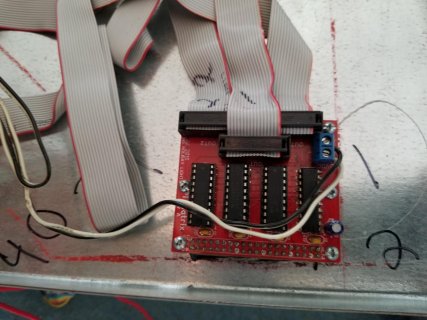
Panel Schmadic.jpg

I have the device attached in the picture. This device will attach to a Raspberri Pi computer and drive 3 rows of RGB panels. It attaches to the HUB 75 input of the rgb matrix panel. In my case, each ribbon attaches to the beginning of a 3 panel wide array of panels.


The chips in the pic covert/buffer 3.3 logic to 5 volt logic. It is similar to what I believe the SmartMatrix/Teensey shield does. Do you have the pin outs for the Teensey SmartMatrix Shield that I can effectively wire to this connector. I suppose I might need three teensey 4.1 devices? I would just like to try the SmartMatrix library on 1 "row" of matricies and see what it is about. To do that, I need the mapping between the hub 75 inputs of a rgb panel and the pins that the teensey 4.1 is manipulating/I should connect to. I would then connect the teensey to the other side of the 40 pin connector for the relevant "Row" driving only 1 ribbon cable.


Is this doeable/available? I need to do this without using the teenset SmartMatrix shield.
 
Is this doeable/available? I need to do this without using the teenset SmartMatrix shield.

Some URLs for the SmartMatrix stuff is:

If you need to test changes on a real board, I'm sure several of us have boards that might be able to try it out. I have a Teensy 4.1 connected to an Adafruit 64x32 3mm pitch display and I have a Adafruit 64x32 4mm pitch display available as well. Note, I'm recovering from surgery, and right now I'm doing fine and hopefully things won't get worse. I also have used a Teensy 4.0 on the SmartMatrix shield.

Here is the header file for the Teensy 4 for the SmartMatrix shield (MatrixHardware_Teensy4_ShieldV5.h):

Code:
/*
 * SmartMatrix Library - Hardware-Specific Header File (for SmartMatrix Shield for Teensy 4 V5)
 *
 * Copyright (c) 2020 Louis Beaudoin (Pixelmatix)
 *
 * Permission is hereby granted, free of charge, to any person obtaining a copy of
 * this software and associated documentation files (the "Software"), to deal in
 * the Software without restriction, including without limitation the rights to
 * use, copy, modify, merge, publish, distribute, sublicense, and/or sell copies of
 * the Software, and to permit persons to whom the Software is furnished to do so,
 * subject to the following conditions:
 *
 * The above copyright notice and this permission notice shall be included in all
 * copies or substantial portions of the Software.
 *
 * THE SOFTWARE IS PROVIDED "AS IS", WITHOUT WARRANTY OF ANY KIND, EXPRESS OR
 * IMPLIED, INCLUDING BUT NOT LIMITED TO THE WARRANTIES OF MERCHANTABILITY, FITNESS
 * FOR A PARTICULAR PURPOSE AND NONINFRINGEMENT. IN NO EVENT SHALL THE AUTHORS OR
 * COPYRIGHT HOLDERS BE LIABLE FOR ANY CLAIM, DAMAGES OR OTHER LIABILITY, WHETHER
 * IN AN ACTION OF CONTRACT, TORT OR OTHERWISE, ARISING FROM, OUT OF OR IN
 * CONNECTION WITH THE SOFTWARE OR THE USE OR OTHER DEALINGS IN THE SOFTWARE.
 */

// Hardware-specific header file for the SmartLED Shield for Teensy 4 (V5):
//    Only Teensy 4.0/4.1 models are supported.
//
// Some of the pin assignments can be changed using solderable jumpers on the adapter board:
// JP4:
//    Default: Pin 7 connected to BUFFER_CLK, Pin 8 free
//    Alt: Pin 8 connected to BUFFER_CLK, Pin 7 free
//      To use the alternate clock pin, in addition to soldering the jumper you must set flag SMARTMATRIX_OPTIONS_T4_CLK_PIN_ALT in kMatrixOptions
// JP2 & JP3:
//    Default: Pin 4 connected to APA_CLK, Pin 5 connected to APA_DAT (intended for APA102 driving via SPI emulation), LED Matrix is drivable at the same time
//    Alt: Pins 4 & 5 free, Pin 13 connected to APA_CLK, Pin 11 connected to APA_DAT (intended for APA102 driving via hardware SPI), LED Matrix not drivable at the same time

// Note: only one MatrixHardware_*.h file should be included per project

#ifndef MATRIX_HARDWARE_H
#define MATRIX_HARDWARE_H

#pragma message "MatrixHardware: SmartLED Shield for Teensy 4 (V5)"

/* an advanced user may need to tweak these values */

// size of latch pulse - can be short for V4 shield which doesn't need to update ADDX lines during latch pulse
// 20 is minimum working value on DP5020B panel
// set to 100 for improved support with FM6126A panel
// don't exceed 150 to avoid interference between latch and data transfer
#define LATCH_TIMER_PULSE_WIDTH_NS 100

// max delay from rising edge of latch pulse to falling edge of first pixel clock
// increase this value if DMA use is delaying clock
// Measured 220 ns delay at 600 MHz clock speed, 160 ns at 816 MHz. Slower speeds are not supported.
// Using larger delay for safety.
#define LATCH_TO_CLK_DELAY_NS 400

// Pixel clock frequency is generated using the 480 MHz PLL3 clock and a divide-by-n counter. Frequency is independent of CPU clock speed.
// Must increment divider value by 2 (division ratio is always even)
// Minimum tested working value is 20 (corresponding to 24 MHz clock frequency) on DP5020B panel
// Using value of 26 (corresponding to 18.462 MHz clock frequency) to improve stability and reduce glitching
// Larger values may be more stable, but will decrease maximum refresh rate
#define FLEXIO_CLOCK_DIVIDER 26

// Amount of time required to transfer 32 pixels
// Adding 200 ns overhead time to improve stability
#define PANEL_32_PIXELDATA_TRANSFER_MAXIMUM_NS  ((32*FLEXIO_CLOCK_DIVIDER*1000/480) + 200)

/* this section describes how the microcontroller is attached to the display */

// these defines control the color channel assignments - if your panel has non-standard RGB order, swap signals here
#define R_0_SIGNAL    FLEXIO_PIN_R0_TEENSY_PIN
#define G_0_SIGNAL    FLEXIO_PIN_G0_TEENSY_PIN
#define B_0_SIGNAL    FLEXIO_PIN_B0_TEENSY_PIN
#define R_1_SIGNAL    FLEXIO_PIN_R1_TEENSY_PIN
#define G_1_SIGNAL    FLEXIO_PIN_G1_TEENSY_PIN
#define B_1_SIGNAL    FLEXIO_PIN_B1_TEENSY_PIN

//#define DEBUG_PINS_ENABLED
#define DEBUG_PIN_1 0
#define DEBUG_PIN_2 1
#define DEBUG_PIN_3 23

/************ The below definitions are unlikely to be useful if changed **************/

// active pin number definitions
// data bit order is calculated in setup using the pin number definitions and color channel assignments
// these pin definitions are also manually used to reset FM6126A panels
#define FLEXPWM_PIN_OE_TEENSY_PIN       2
#define FLEXPWM_PIN_LATCH_TEENSY_PIN    3
#define FLEXIO_PIN_CLK_TEENSY_PIN       7
#define FLEXIO_PIN_CLK_TEENSY_PIN_ALT   8
#define FLEXIO_PIN_B0_TEENSY_PIN        10
#define FLEXIO_PIN_R0_TEENSY_PIN        6
#define FLEXIO_PIN_R1_TEENSY_PIN        12
#define FLEXIO_PIN_G0_TEENSY_PIN        9
#define FLEXIO_PIN_G1_TEENSY_PIN        11
#define FLEXIO_PIN_B1_TEENSY_PIN        13

#define SMARTLED_APA_ENABLED_BY_DEFAULT true
#define SMARTLED_APA_ENABLE_PIN         22
#define FLEXIO_PIN_APA102_CLK           4
#define FLEXIO_PIN_APA102_DAT           5

#define ADDX_0_SIGNAL   FLEXIO_PIN_R0_TEENSY_PIN
#define ADDX_1_SIGNAL   FLEXIO_PIN_G0_TEENSY_PIN
#define ADDX_2_SIGNAL   FLEXIO_PIN_B0_TEENSY_PIN
#define ADDX_3_SIGNAL   FLEXIO_PIN_R1_TEENSY_PIN
#define ADDX_4_SIGNAL   FLEXIO_PIN_G1_TEENSY_PIN

#else
    #pragma GCC error "Multiple MatrixHardware*.h files included"
#endif
 
There must be some amount of time that the shift register muse see a value before it effectively latches it and one can move on? I was looking to use 60 Frames per second. I obviously can use a lower frame rate, but I was just curious, as my tv probably does 60 FPS. I wondered what the upper limit on these panels are as far as update.

There is a clock rate limit for a single chain of HUB75 RGB panels. SmartMatrix library can get pretty close to this limit, amounting to 96 million pixels * color bits per second. With 36 bit "high color settings" and 9*32*64 pixels, you should be able to achieve a screen refresh rate of 144 Hz with only a single Teensy 4.

In fact you may need to increase your frame rate above 200 Hz to avoid noticeable flicker with these panels. 60 Hz is certainly not enough. To increase the frame rate, you would either need to split the chain like discussed previously, or you could reduce the color depth to 21 or 24 bits which should still look quite good except when distinguishing dark colors.

Taking good photos or videos of the panels usually requires an even higher frame rate as well...

Some speed results were posted here:

https://community.pixelmatix.com/t/teensy-4-0-released/498/62?u=easone
 
Thanks for all the help, I will have to look at the schematic of the Teensy shield. I was hoping to use just the library to connect the Teensey directly to a single RGB panel on its HUB 75 input and test.

If that worked, then I will look into the differences between the Teensy shield and my board above. From what I remember, all the board above is doing is making the HUB75 inputs for 3 separate chains available on a 40 pin connector. All the same signals in one HUB75 input are present on some pins of the 40 pin connector above. The only other thing the board above does is level shift. Not sure how much delay that adds to the signal going thru.

I left off trying to connect an FPGA to the above board on a 40 pin connector and drive it, but there were timing issues with the FPGA board that made it more challenging . I think I remember connecting an arduino to the 40 pin header above and working with one panel, but the arduino is slow and its library stunk. The raspberry pi library was good, but slow. I suspected the FPGA would be the fastest, but more complex. My plan was to have the raspberry pi write to sdram on the FPGA and it would drive that panel on the 40 pin interface as breakneck speeds. I suspected that it can be too fast for the chips on the chains, and slowing it was were I left off, as well as figuring out how to sync the 3 HUB75 rows to SDRAM reads on the FPGA. Just seems simpler to work with the teensey and see what it can do with this smartmatrix library. I will still need the raspberry pi in the picture for richness of programming environment and ui. Ill look at the schmedic of the Teensy shield and try and understand what row address latching hardware is and how it works with teh expected HUB75 inputs on a single chain. Thank you
 
No problem. In brief, the panel takes 14 inputs: 6 RGB lines, 5 row address lines, clock (CLK), output enable (OE), and latch (LAT). The Teensy shield drives these signals using only 9 Teensy pins, by having 5 of the RGB lines also drive the address lines through a latch chip. The LAT signal simultaneously latches the RGB data into the panel, and latches the address lines so the panel displays the data on the correct row. The SmartMatrix library is designed to output address data on the RGB lines at the correct moment for this to work.

By the way, the "APA102 Buffers" section of the schematic can be safely ignored - it's not used when driving HUB75 panels.
 
Status
Not open for further replies.
Back
Top