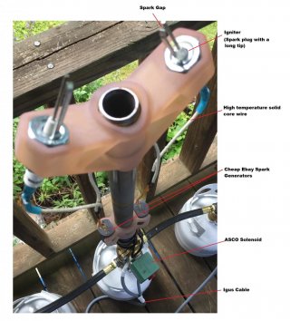
Full disclaimer: I do not suggest building anything that is discussed below. I am aware of the danger inherent in anything that creates flames. Please don't try this at home, unless you really understand what you are doing, and then please take proper safety precautions. I am currently testing my system using only compressed air. I will do this until I am confident in the electrical portion of the design. I assume all responsibility for my personal safety and those around me. You should do the same.
I have built a flame effect device that uses a Teensy 4.1 to control up to eight gas valve solenoids and 16 spark modules. I am having trouble with what I think is high frequency/high voltage noise generated by the spark modules. I am looking for suggestions on how to reduce this noise.
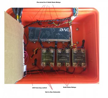
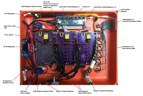
I am using the Teensy 4.1 to communicate through serial to three daisy-chained 74HC595 shift register boards. The shift register boards use mosfets on the outputs. The first two boards control the 16 spark modules. The third board controls 8 solid state relays that then control the 8 24V gas solenoids. Maybe this isn't the best way to do this, I am no electrical engineer.
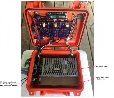
The system uses 48V input from a Mean Well 120v power supply (I plan to eventually replace this with a 48v battery). That is reduced to 24v by a second Mean Well power supply. Then there are three voltage regulators; a 3.3v regulator sends power to the three shift registers VCC, a 5v regulator powers the Teensy 4.1, and a 5V 9A regulator sends power to all of the mosfets.
I am using the serial monitor to verify that the button presses and output to shift registers is correct. The serial monitor always prints the correct button press and 8bit variable, so I don't think my problem is in my programming or serial output.
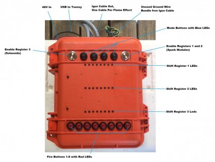
The shift register boards have led indicators on all of the 74HC595 outputs. The 74HC595s have output enable pins. I have these connected to buttons that either ground or connect this pin to 3.3v (VCC on shift register board). When I only activate the gas solenoids, everything works properly, but if I activate any one spark module, many of the 74HC595 output leds will flicker and the corresponding spark modules and gas solenoids will sputter/spark. I have 6' long 20 gauge Igus style multi conductor cables running individually to each spark module. Putting distance between these cables seemed to help but only had maybe a 50% improvement in perceived noise.
I am not an electrical engineer, so I am a bit unsure of what to try here. I don't know what frequency or voltage the spark modules output. Should I try adding ferrite beads somewhere? Would adding a capacitor between the inputs to each spark generator help? Do I need shielding for my cables? I'm just not sure where to start.
Code attached. Links below.
3.3V 2.6A Regulator (up to 36V input): https://www.pololu.com/product/2857
5V 2.5A Regulator (up to 36V input): https://www.pololu.com/product/2858
5V 9A Regulator (input 5-38V): https://www.pololu.com/product/2866
Shift registor/Mosfet boards:https://www.summet.com/blog/2012/08/05/serial-shift-register-mosfet-driver-version-1-1/
Spark Generator: https://www.ebay.com/sch/i.html?_from=R40&_trksid=p2553889.m570.l1313&_nkw=1PCS+DC+3v-6v+to+400kV+400000V+Boost+Step-up+Power+Module+High-voltage+Generator&_sacat=0
Solid State Relay: https://www.digikey.com/en/products/detail/sensata-crydom/DC60S3/221844
ASCO 8210g076 Fuel Gas Solenoid Valve 24V 10.1Watts :https://www.emerson.com/documents/automation/catalog-gas-shutoff-series-210-asco-en-4290880.pdf
View attachment Fire_Effect_Shift_Registers.ino
Last edited:


