Marathonman
Well-known member
I have had a Teensy 4.0 running my SPI shift register code for many months now. problem is i decided to step up to the Teensy 4.1 forward thinking to adding external current, voltage, ethernet and display for monitoring. problem is the power i am getting from the Teensy 4.1 is severely lacking to say the least. the demo i have on youtube is made with a Teensy 4.0 and the LED's are very bright, almost to bright yet with the Teensy 4.1 i can barely see the LED's and can not run the whole set of 8 shift registers at the same time without the Teensy shutting down.
I am extremely upset to say the least that the 4.1 is so lacking in power, irregardless of whether i purchased from adifuit or not, (here no stock) it still should not be so lacking in power. the board i have is a custom 8 shift register board that will be tied to a high side transistor board but as of this moment i am stuck scratching my head.
Code;
Thanks in advance,
Marathonman
I am extremely upset to say the least that the 4.1 is so lacking in power, irregardless of whether i purchased from adifuit or not, (here no stock) it still should not be so lacking in power. the board i have is a custom 8 shift register board that will be tied to a high side transistor board but as of this moment i am stuck scratching my head.
Code;
Code:
// This sketch controls multiple 74HC595 shift registers in cascade to electronically control Figuera's active inductor
// controller by switching on taps located on part G connected to transistors in a "Make Before Break" scenario. by changing
// tap locations continuously changes inductance which controls current flow of the primaries.
// this sketch utilizes timing overlap to eliminate back Bemf or Cemf that would occur with single on off tap. it mimics
// the brush rotation of a mechanical rotating brush thus creates a continuous increase/decrease current through the primaries.
// this sketch is distributed freely but if you use this program then post build on line give credit where credit is
// due and not claim as your own design.
// to adapt to your build change pin numbers, delay time.
// developed for the electronic Figuera community by (DL)aka Marathonman with all technical help and coding of PaulRB on Arduiono.cc
// Forum.
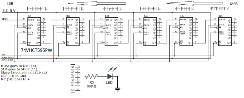
// Mosi to DS in pin 14 on 74HC595
// SCK to Seial Clock SHCk Shift Clock pin 11 on 74HC595
// SS, CS or any latch pin declared output to STCK latch pin 12 on 74HC595
#include <SPI.h>
unsigned long long int registerBuffer = 0b11;
byte shiftPos = 0;
bool shiftingLeft = true;
unsigned long long int lastUpdate;
const unsigned long long updatePeriod = 100000ULL; // change this microseconds figure to what you need for speed.
const byte latchPin = 10; // this can be changed to what ever latch pin you want.
void setup() {
Serial.begin(115200); // use you SPI pins found on all Arduino's. coding will automatically take care of the rest if SPI0 pins
// used.Mosi0,SCk0 Ect...
SPI.begin();
SPI.beginTransaction(SPISettings(1000000, MSBFIRST, SPI_MODE0));
pinMode(latchPin, OUTPUT); // pinMode can be changed to direct port manipulation (Faster)if port is known then that of digital
// read/wright.
}
void loop() {
if (micros() - lastUpdate > updatePeriod) { //Is it time to update the registers?
lastUpdate = micros();
//Shift the register left or right
if (shiftingLeft) {
registerBuffer <<= 1; //Shift 1 place to left
if (++shiftPos == 62 // < add how ever many pins or taps on part G you have up to unsigned long long of 64 buffer minus 2.
) shiftingLeft = false; //Time to switch direction?
}
else {
registerBuffer >>= 1; //Shift 1 place to right
if (--shiftPos == 0) shiftingLeft = true; //Time to switch direction?
}
unsigned long long int temp = registerBuffer; //Take a copy of the buffer
SPI.transfer(&temp, 8); //Send the buffer to the registers // This must match your Shift Register count 1 through 8
digitalWrite(latchPin, HIGH); //Latch the updated values into the register's output pins
delayMicroseconds(1);
digitalWrite(latchPin, LOW);
}
}Thanks in advance,
Marathonman