LIS3DH accelerometer not working in SPI mode with Teensy 4.1

Status
Not open for further replies.

Girija

Member
I am using the Adafruit LIS3DH accelerometer. I got it working with the Arduino UNO with both I2C and SPI.
I decided to switch to the Teensy since I will eventually need to log to an SD card at higher speeds.

I managed to get it working with I2C on the Teensy 4.1
However, am unable to get it working in the SPI mode.
Note that I initially used pins 10 -13 for SPI. But based on similar forum discussions where a bad connection was suggested as the possible problem, I decided to try CS1-SCK1. I have since swapped back to the Arduino and tried 2 other LIS3DH adafruit boards. They continue to work with the Arduino; but not with the Teensy.
Note that I purchased a pre-soldered Teensy and the LIS3DH soldering must be OK since it worked with the Arduino.
The code and the console output are shown below. I have tried with default settings without using the Sections of the code in bold and it still doesn't work.
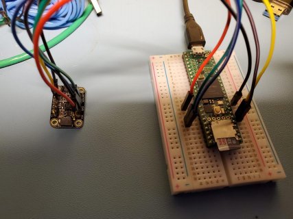
TeensyLIS3DH.jpg


// Basic demo for accelerometer readings from Adafruit LIS3DH

#include <Wire.h>
#include <SPI.h>
#include <Adafruit_LIS3DH.h>
#include <Adafruit_Sensor.h>

// Used for software SPI
#define LIS3DH_CLK 27
#define LIS3DH_MISO 39
#define LIS3DH_MOSI 26
// Used for hardware & software SPI
#define LIS3DH_CS 38

// software SPI
Adafruit_LIS3DH lis = Adafruit_LIS3DH(LIS3DH_CS, LIS3DH_MOSI, LIS3DH_MISO, LIS3DH_CLK);
// hardware SPI
//Adafruit_LIS3DH lis = Adafruit_LIS3DH(LIS3DH_CS);
// I2C
//Adafruit_LIS3DH lis = Adafruit_LIS3DH();

void setup(void) {
Serial.begin(115200);
while (!Serial) delay(10); // will pause Zero, Leonardo, etc until serial console opens

SPI.begin();
pinMode(LIS3DH_CLK, OUTPUT);
pinMode(LIS3DH_MISO, INPUT);
pinMode(LIS3DH_MOSI, OUTPUT);
pinMode(LIS3DH_CS, OUTPUT);


Serial.println("one");
//SPI.beginTransaction(SPISettings(10000000, MSBFIRST, SPI_MODE0));

Serial.println("two");
//digitalWrite(LIS3DH_CS, HIGH);

digitalWrite(LIS3DH_CS, LOW);
lis.setDataRate(LIS3DH_DATARATE_LOWPOWER_5KHZ);
Serial.println("four");
//SPI.transfer(0x20);

//Serial.println("five");
//SPI.transfer(0x8F);


Serial.println("three");
Serial.println("LIS3DH test!");

if (! lis.begin(0x18)) { // change this to 0x19 for alternative i2c address
Serial.println("Couldnt start");
//while (1) yield();
}
Serial.println("LIS3DH found!");

// lis.setRange(LIS3DH_RANGE_4_G); // 2, 4, 8 or 16 G!

Serial.print("Range = "); Serial.print(2 << lis.getRange());
Serial.println("G");

// lis.setDataRate(LIS3DH_DATARATE_50_HZ);
Serial.print("Data rate set to: ");


-----------------------------------------------------------
OUTPUT on Serial Port is below
-----------------------------------------------------------
one

two

four

three

LIS3DH test!

Couldnt start

LIS3DH found!

Range = 2G

Data rate set to: Powered Down

X: 0 Y: 0 Z: 0 X: 0.00 Y: 0.00 Z: 0.00 m/s^2
 
With those pins that is using SPI1 not SPI:

Not finding a clear single example ... but something like::
Code:
		SPI1.begin();

And using ALT pin 39 for SPI1:
Code:
SPI1.setMISO(39);

Make those changes as "SPI1" and don't do pinMode on the pins as the .begin() code should take care of that, except for the CS of LIS3DH_CS.
 
Thanks for the quick response.
I realized I was using the ALT pins for SPI1.
So I corrected that to now use 0,1,26 and 27.
Changed SPI.begin to SPI1.begin like you suggested.

Still no luck. The latest code is below - I've removed the debug statements:

-------------------------------------
#include <Wire.h>
#include <SPI.h>
#include <Adafruit_LIS3DH.h>
#include <Adafruit_Sensor.h>

// Used for software SPI
#define LIS3DH_CLK 27
#define LIS3DH_MISO 1
#define LIS3DH_MOSI 26
// Used for hardware & software SPI
#define LIS3DH_CS 0

// software SPI
Adafruit_LIS3DH lis = Adafruit_LIS3DH(LIS3DH_CS, LIS3DH_MOSI, LIS3DH_MISO, LIS3DH_CLK);
// hardware SPI
//Adafruit_LIS3DH lis = Adafruit_LIS3DH(LIS3DH_CS);
// I2C
//Adafruit_LIS3DH lis = Adafruit_LIS3DH();

void setup(void) {
Serial.begin(115200);
while (!Serial) delay(10); // will pause Zero, Leonardo, etc until serial console opens

SPI1.begin();


digitalWrite(LIS3DH_CS, LOW);
lis.setDataRate(LIS3DH_DATARATE_LOWPOWER_5KHZ);

Serial.println("LIS3DH test!");

if (! lis.begin(0x18)) { // change this to 0x19 for alternative i2c address
Serial.println("Couldnt start");
//while (1) yield();
}
Serial.println("LIS3DH found!");
 
No. It did not work with those SPI pins of 10-13.
Tried including Adafruit_SPIDevice.h
That didn't work either
 
If SPI didn't work then SPI1 not working isn't a surprise.

I see this sparkfun.com/tutorials/lis3dh-hookup-guide

Not sure if that might offer any help - it notes their device is 3.3V - of course with T_4.1 it has to work with 3.3V - versus UNO at 5V.

Not having one here or having used them on SPI - not sure if the hardware is good at 3.3V and if maybe the Sparkfun driver might be a better fit?
 
Turns out, one of these was at hand! I have the prior PRE-qwiic plug board from AdaFruit, that otherwise wires and works the same.

Bad news it soldered and wired it up on SPI with no success :(

Note: this version of the constructor has to be used for hardware SPI - if it worked the 2nd param should allow SPI1 :: Adafruit_LIS3DH lis = Adafruit_LIS3DH(LIS3DH_CS, &SPI);
>> Using the explicit PINS version uses software SPI as noted and not sure that would work on T_4.1

But Adafruit_LIS3DH::begin is failing to get a usable SPI from : spi_dev = new Adafruit_SPIDevice(_cs, ... when it then does if (!spi_dev->begin()) { in :: ...\libraries\Adafruit_LIS3DH\Adafruit_LIS3DH.cpp

The Sparkfun was tried as well - also on SPI to begin with. It shows support added for T_3.2 ... but about 5 years ago.
Arduino IDE 1.6.4
Teensy loader 1.23

I find one thread using this from 2017 with te AdaFruit code and it seems the LIS3DH() was workng on T_3.6?
>> noInterrupts()-allowing-some-interrupts-LIS3DH-NRF24L01-Teensy-3-6
 
Don't think I have a Adafruit LIS3DH board that I can test with.

Wondering if it might be a problem with some setting in their SPI library? I do see that they have ifdef for fastSPI_IO but not sure if thats a problem with the T4 or if its even being used.

You might try using the Sparkfun LIS3DH library. https://github.com/sparkfun/SparkFun_LIS3DH_Arduino_Library/tree/master/examples

The examples are geared to I2C but easy enough to change. Would start with their examples on SPI and go from there. Would use this constructor for begin:
Code:
LIS3DH Sensor( SPI_MODE, CS_PIN);
 
Hardware SPI worked! This is even better since it is faster than software SPI - though I will have to learn more about the actual differences. I'm new to this. Thanks!!!!
 
Hardware SPI worked! This is even better since it is faster than software SPI - though I will have to learn more about the actual differences. I'm new to this. Thanks!!!!

That is good news! Can you post details on the working solution?

I ran out of time yesterday.
 
I used the same wiring as the initial software SPI wiring using pins 10-13. I just commented off the 3 pin definitions for software SPI and only left the one for the Chip Select pin (10). That's it! Code is attached.

Apologies for the delay. I was adding code to log data to a file on the SD card along with millis() timestamp.
This should give an idea about the speed at which the 'data reading + data logging' is executed for the hardware SPI connection. I am seeing roughly 5500 samples/second.
The code has a loop of 10000 and you can look at the millis for the first and last reading to calculate the total time to run through 10000 readings.

The execution is complete once you see 'Done' (non-stop) on the console.....not exactly elegant. I have managed to open and close the logging file only once to reduce associated delays.
 

Attachments

  • T4.1LIS3DH-HardwareSPI-SDcard.ino
    3.6 KB · Views: 97
opps ... BAD WIRING ... T_4.1 pin numbers too small. Pins 10/11/12 were shifted one pin lower ... of course also had SDA and SDO swapped ...

Indeed that sketch as posted works.
Code:
		X: 
-6.33
 	Y: 
7.25
 	Z: 
-0.15
2398
		X: 
-6.33
 	Y: 
7.25
 	Z: 
-0.15
2398

SPI Wiring
Code:
sensors_LIS3DH_Arduino_SPI_bb.jpg
sensors_LIS3DH_Arduino_SPI_bb.jpgsensors_LIS3DH_original_Arduino_SPI_bb.jpg	
Connect Vin to the power supply, 3V or 5V is fine. Use the same voltage that the microcontroller logic is based off of. For most Arduinos, that is 5V
Connect GND to common power/data ground
Connect the SCL (SCK) pin to Digital #13 but any pin can be used later
Connect the SDO pin to Digital #12 but any pin can be used later
Connect the SDA (SDI) pin to Digital #11 but any pin can be used later
Connect the CS pin Digital #10 but any pin can be used later
 
Forgot to mention. Another difference of course is I commented off the Adafruit_LIS3DH variable definition of lis and used the hardware SPI one instead.

In case this interests you, I modified to code to remove all SD card and console logging with the exception of the time at the start and end ..............and it takes about 831 milliseconds to read 10000 times over hardware SPI. This effectively gives 12K samples per second. Kind of meaningless given the LIS3DH has a max ADC ability of 5KHz. But it tells you how fast the hardware SPI is for the default Teensy 4.1 clock rate. I haven't changed the Teensy's clock and haven't looked into that yet.
 
Quick edits - Moved pins to SPI1 - still with CS at 10:
Code:
Adafruit_LIS3DH lis = Adafruit_LIS3DH(LIS3DH_CS, &SPI1);

Added Serial print to see data without SD swapping and made this single line change as suggested before:
Code:
	X: 0.27 	Y: 9.58 	Z: 4.731808
	X: 0.27 	Y: 9.58 	Z: 4.731808
	X: 0.27 	Y: 9.58 	Z: 4.731808
	X: 0.27 	Y: 9.58 	Z: 4.731808
	X: 0.27 	Y: 9.58 	Z: 4.731808
	X: 0.27 	Y: 9.58 	Z: 4.731808
	X: 0.27 	Y: 9.58 	Z: 4.731809
	X: 0.72 	Y: 10.29 	Z: 5.081809
	X: 0.72 	Y: 10.29 	Z: 5.081809

So this one is hardware SPI1.........right?
 
Glad to help - I knew I should have checked my wiring last night but it was LATE ... and expecting it to not work - I wrongly excepted it not working :(

But thanks to you as well! I had two of those sensors still in the wrapper sitting by my desk in a project box ... for a project that should be getting my attention.

I did this quick edit to loop to limit the Sensor read to 1000/sec and also to limit prints until there is a measurable motion detected.

The DIFF needed is 0.3 on any axis - and that only takes a simple tap:
Code:
sensors_event_t event0;
elapsedMicros myWait;
void loop() {
  if ( myWait >= 1000 ) {
    myWait = 0;
    uint32_t xx, yy, zz;
    lis.read();      // get X Y and Z data at once
    sensors_event_t event;
    lis.getEvent(&event);
    xx = event.acceleration.x - event0.acceleration.x;
    yy = event.acceleration.y - event0.acceleration.y;
    zz = event.acceleration.z - event0.acceleration.z;
    if ( abs(10 * xx) > 3 || abs(10 * yy) > 3 || abs(10 * zz) > 3  ) {
      Serial.print("\tX: ");
      Serial.print(event.acceleration.x);
      Serial.print(" \tY: ");
      Serial.print(event.acceleration.y);
      Serial.print(" \tZ: ");
      Serial.print(event.acceleration.z);
      Serial.print(" \tms: ");
      Serial.println(millis());
    }
    event0.acceleration.x = event.acceleration.x;
    event0.acceleration.y = event.acceleration.y;
    event0.acceleration.z = event.acceleration.z;
  }
}

<edit> - just looked and the sensor values are float.
 
FWIW - the Sparkfun code works as well when properly wired to SPI. Though, as written, it is hardcoded for "SPI." unlike the AdaFruit library that allows passing &SPI? as desired.

And the posted example was way more fun as edited for p#19 to only SPEW on a 0.3 change on any axis.
 
Status
Not open for further replies.
Back
Top