snowsh
Well-known member

I am at the end of my tether. I have spent the last day trying to get this work.....
I'm developing a project using a teensy 4.1....
I have my mux running using 2 cd74hc4067 16 channel MUX. I based my MUx on this page https://forum.pjrc.com/threads/47074l-Teensy-LC-and-74HC4067-16-channel-multiplexer-wiring
Its all good and been working fine for weeks. My project has grown so I have added a third MUX and built a new vero board prototype.. I suspect this is where my issue lies, but I am not sure...
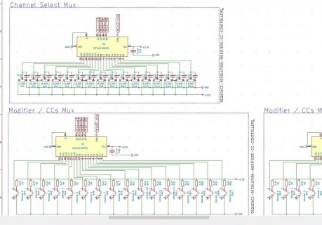
Please take a glance over my schematic....
issue:
the mux is working, but only registering preses on odd number channels, which then trigger the next channel too. ie pressing button 0, triggers 0 and 1.
I have put a counter on my debug, and I see that the serial.print is outputting the 0 read on the correct loop, and then the following loop it goes and fires channel 1.....
I have tested my wiring, tried another teensy 4.1. Everything seems to be right. Whatever I do I keep getting this double hit problem.
My suspicion is the 2.2k pull up resistor is maybe too low? Should I add diodes? But then again these have worked rock solid for weeks now on my two mux board. also, the total lack of response from the odd channels, ie 1,3,5,7....15 is making me doubt its a problem in the board and there is somthing glaring me in the face in the code that I am not seeing because i have gone totally crosseyed....
Stumped.
here is my code (stripped out somewhat as my project is huge) There are several timers that really pay no function in this example, they are for elsewhere in my project.
Code:
/*


   http://www.thebox.myzen.co.uk/Tutorial/Inputs.html --------------------   !!  IMPORTANT !! ------------------

   https://forum.pjrc.com/threads/47074l-Teensy-LC-and-74HC4067-16-channel-multiplexer-wiring

*/

elapsedMillis currentMillis = 0;

unsigned long buttonDebounceDelay = 250;

int MuxDumpCounter = 0;

const int muxTimeMin = 200;                                // minimum micro-seconds between MUX reads - higher values should be more stable but less responsive

const int M_PINS = 16;                                    // number of MUX PINS

const int MUX_COUNT = 3;                                  // number of MUX

const int SO_PINS[4] = {32, 31, 30, 29}; // {29, 30, 31, 32};                  //array size is (M_PINS)^-2

const int MUX_READ[MUX_COUNT] = {40, 23, A17};                // Pins to SIGNAL on MUX - I only have one MUX to test so I ran all to A0 for testing

const bool muxAnalogType[MUX_COUNT] = {false, false, true};      // false digital. true analog

const int dbt = 12;                                       // a threshold value for how big the dead-band is before recalc - set higher to minimize excess MIDI if inputs are noisy

//------------------------------------------------------------------------  MUX variables

unsigned long lastMuxReading[MUX_COUNT][M_PINS] = {0};

int muxReading[MUX_COUNT][M_PINS] = {0};

int muxReadingLagged[MUX_COUNT][M_PINS] = {0};

int lastKeypadMuxPress = 0;                               // used to track the data input keyboard for multiple presses. assume mux 0 for the key

int muxPressAr[MUX_COUNT][M_PINS] = {0};                  // to  track if the buttons have been pressed

int muxAnalogAr[MUX_COUNT][M_PINS] = {0};                 // to track if a knob value has changed

bool muxHoldAr[MUX_COUNT][M_PINS] = {false};              // used to override reset of the mux - if its being held down

unsigned long muxDown[MUX_COUNT][M_PINS] = {0};           // used to track key down of the mux -  the time it was pressed

elapsedMicros muxUpdated;                                 // timer counter (micros)

int j = 0;                                                // index for mux chanel select loop - needs to be global THIS IS KEY! - 'j' is not used in a 'for' statement but is incremented with each main loop call


void setup()
{
  setupMuxPins();

}

void loop()
{
  currentMillis = millis();
  getMUXData();
}


//------------------------------------------------------------------------  setup

void setupMuxPins()
{
  for (int i = 0; i < 4; i++)                                                   //set SO pins for MUX control as output
  {
    pinMode(SO_PINS[i], OUTPUT);
  }
  for (int i = 0; i < MUX_COUNT; i++)
  {
    pinMode(MUX_READ[i], INPUT);
  }
}

//------------------------------------------------------------------------  mux

void getMUXData()
{
  if (muxUpdated > muxTimeMin)
  {
    for (int i = 0; i < MUX_COUNT; i++)
    {
      if (muxAnalogType[i] == true)
      {
        muxReading[i][j] = analogRead(MUX_READ[i]);

        if (abs(muxReading[i][j] - muxReadingLagged[i][j]) > dbt )              // analog read
        {
          if (currentMillis - lastMuxReading[i][j] > buttonDebounceDelay)
          {
            muxAnalogChannelfuctionHandler(i, j);

            muxReadingLagged[i][j] = muxReading[i][j];

            muxPressAr[i][j] = muxReading[i][j];

            lastMuxReading[i][j] = currentMillis;
          }
        }
      }
      else                                                                      // digital pins
      {
        muxReading[i][j] = digitalRead(MUX_READ[i]) == LOW ? 1 : 0;

        if (muxReading[i][j] == 1)                                              // digital read
        {
          if (currentMillis - lastMuxReading[i][j] > buttonDebounceDelay)
          {
            muxDown[i][j] = currentMillis;                                     // log the keydown

            muxHoldAr[i][j] = true;

            muxReadingLagged[i][j] = muxReading[i][j];

            muxPressAr[i][j] = 1;

            muxDigitalChannelfuctionHandler(i, j);                              // this will handle things like enable,solo,mute etc using the channel buttons

            lastMuxReading[i][j] = currentMillis;
          }
        }
        else
        {
          muxDown[i][j] = 0;                                                   // the key is not pressed set to 0

          muxHoldAr[i][j] = false;
        }
      }
    }

    muxUpdated = 0;                                                             //reset timer

    j++;                                                                        // increment global counter variable before setting up MUX control for the next pass!

    if (j >= M_PINS)
    {
      j = 0;                                                                    // rollover at 16
    }

    for (int i = 0; i < 4; i++)
    {

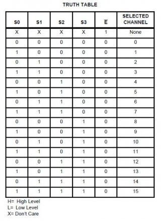
      digitalWrite(SO_PINS[i], (boolean) (j & (int) pow(2, i)));                // bit-fiddle to set the i-th pin to HIGH IFF binary version of j contains i-th multiplier (i-th power of 2)
    }
  }
}


//------------------------------------------------------------------------  analog faders

void muxAnalogChannelfuctionHandler(int muxId, int muxPin)
{
// commented out for this example.  usbMIDI.sendControlChange(ccControllerArrayMessageId[muxPin], muxReading[muxId][muxPin] >> 3, ccControllerArrayMidiChannel[muxPin]);
}

//------------------------------------------------------------------------  digital mux buttons


void muxDigitalChannelfuctionHandler(int muxId, int muxPin)
{
    Serial.print("MuxDumpCounter");
    Serial.println(MuxDumpCounter);

    Serial.print("muxId: ");
    Serial.print(muxId);
    Serial.print("  muxPin: ");
    Serial.println(muxPin);

    MuxDumpCounter++;
}


void resetMux(int i, int j)
{
  muxPressAr[i][j] = 0;
}

void initMux()
{
  for (int i = 0; i < MUX_COUNT; i++)
  {
    for (int j = 0; j < M_PINS; j++)
    {
      muxPressAr[i][j] = 0;

      muxAnalogAr[i][j] = {0};
    }
  }
  dumpMux();
}

void resetAllMux()
{
  for (int i = 0; i < MUX_COUNT; i++)
  {
    for (int j = 0; j < M_PINS; j++)
    {
      if (!muxHoldAr[i][j]) muxPressAr[i][j] = 0;
    }
  }
}

void dumpMux()
{
  for (int i = 0; i < MUX_COUNT; i++)
  {
    for (int j = 0; j < M_PINS; j++)
    {
      Serial.print("MUX_COUNT : ");
      Serial.print(i);
      Serial.print(" M_PINS : ");
      Serial.print(j);
      Serial.print(" : ");
      Serial.println(muxPressAr[i][j]);
    }
    Serial.println("-------------------------------------------------------- ");
  }
  Serial.println("-------------------------------------------------------- end dump");
}

