T3.2: AnalogRead() gives wrong values

Status
Not open for further replies.

daanv

Member
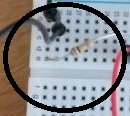
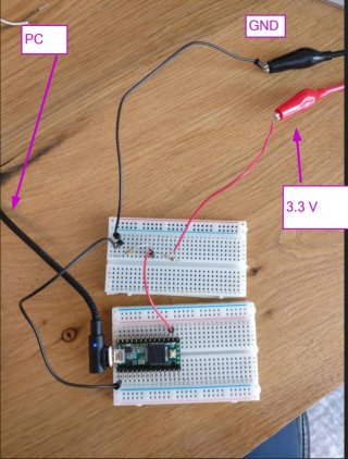
I am using a Teensy 3.2, and have connected a voltage divider consisting of 2 resistors of 100 kOhm each. See image. A voltage of 3.3 V is applied.
Board is connected to laptop via USB.
I measured the analog reference voltage pin (AREF) on the back of the board, which is 3.26 V. I am dividing the analogRead value by 1024 due to 10 bit resolution, and multiplying by 2 for the voltage divider.
The output value I am expecting is 3.26 V, instead I get values that are quite far off (see below). I also tried the same circuit on an Arduino Nano, taking into account 5 V reference voltage rather than 3.3 V, and that did work fine.

Output values.
Code:
2.95
2.84
3.01
2.91
3.06
2.77
2.79
2.82
2.76
2.87
2.78
2.82
2.95
2.75
2.72
2.94
2.94
3.02

See code below.

Code:
void setup() {
  // put your setup code here, to run once:
  Serial.begin(9600); 
  while (!Serial) {
    // wait for Arduino Serial Monitor to be ready
  }
  
}
void loop() {
  // put your main code here, to run repeatedly:

  float bat_v = ((float) analogRead(A0))*(3.27/1024.0)*2.0; 

//  float bat_v = analogRead(A0); 
  Serial.println(bat_v); 

}


2021-05-28 15_10_11-Photos.jpg
 
See code below.

Code:
void setup() {
  // put your setup code here, to run once:
  Serial.begin(9600); 
  while (!Serial) {
    // wait for Arduino Serial Monitor to be ready
  }
  
}
void loop() {
  // put your main code here, to run repeatedly:

  float bat_v = ((float) analogRead(A0))*(3.27/1024.0)*2.0; 

//  float bat_v = analogRead(A0); 
  Serial.println(bat_v); 

}

As noted, 100K is too large for the divider resistors. I don't know if it's true for the T3.2, but on the T4.X
I always add

pinMode(inPin, INPUT_DISABLE);

to make sure only the analog input is connected to the pin. With no pinMode in your setup, you get the startup default, which may have a pulldown resistor enabled to keep the pin from oscillating if not connected.
A pulldown in parallel with your resistor to ground could explain the low values.

For each sample, the ADC connects the input to a sampling capacitor which must charge to the input voltage through the 100K in the limited sampling window. It's a small sampling capacitor, but the window is short and you probably aren't getting enough charge into the capacitor. Thus the recommendation for lower values in the voltage divider.
 
Last edited:
Since this is a low-power application I want to use as large resistor values as possible.

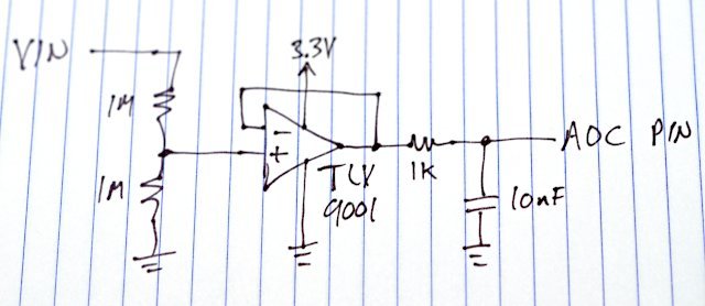
If you're willing to go with a more complex circuit, adding an opamp can give you very low power and also low impedance drive on the ADC pin for better measurements.

opamp.jpg

There are so many opamps on the market, though which can actually be purchased right now is a good question. You want to find one with CMOS inputs, so it will work with large resistors on the voltage divider. Historically non-bipolar inputs meant substantial voltage offset error, but lots of modern CMOS input opamps have voltage error under 1mV. Usually I use TLV9001 when I need this sort of thing, though you can probably find others that consume much less than 60 uA current (and lower than 1 MHz bandwidth which comes with lower current used by the amplifier).

Edit: a part like TLV369 could let you get the total measurement current down to just a couple microamps, and still have 12 kHz bandwidth and not a lot of error & noise added (higher power opamps usually perform better...) Don't skimp on a resistor and capacitor between the opamp and ADC pin, as low power opamps have weaker drive and the ADC is a switched capacitor input.
 
Last edited:
Status
Not open for further replies.
Back
Top