Feasibility/ Implementing SENT protocol

Status
Not open for further replies.

con_103

Member
Implementing SENT protocol - I put a wager on teensy

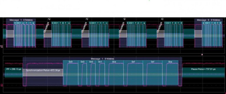
I am trying to determine if I can use my Teensy 3.2 to implement the single wire communication protocol SENT (Single edge nibble transmission). A picture is shown below.
It is essentially a string of Pulses that stores information in the duration from negative edge to negative edge of each pulse. It counts the number of "ticks" in each pulse, which are little sub units of time like seconds on a clock. The number of ticks in a pulse is the data. For data pulses it is 12-27 ticks with 12 representing 0 and 27 representing 15. Each pulse has a predetermined low time at the start of my pulse usually 5 ticks. So for each pulse Low ticks + high ticks = total ticks
Capture.jpg
https://en.wikipedia.org/wiki/SENT_(protocol)


I have a high speed sensor that operates on a .5 us tick time. So I am replicating that sensor, I need to send 4 consecutive pulses, and I am trying to find the best way to do it. I tried simply using delays and digitalWriteFast but I couldn't get sub microsecond delays. I began looking into hardware timers, the PDB has a back to back chain I thought I could use but that is going to require some digging.

But I am just getting started implementing things like this with microcontrollers. So to all your infinite wisdom I ask, what are some of the routes I should take? Maybe there is something I am not even familiar exists that will simplify this task.

We have an engineer here at our company that was adamant this was impossible with the Teensy, I really think he is wrong and I really want to prove him wrong. We have a big bet going that involves public embarrassment if I get it working :D
 
Last edited:
I got it to work.
Here is the code if it helps anyone else trying to do something similar. It is using the FTM timers to implement the protocol.

The code is a bit dirty, but I just noticed some other folks asking about sent on here. So maybe this can help.

Code:
int a=0;
 bool up= 1;

 int SENT_MESSAGE_ARRAY[7];
 int wait_time = 103; //us
 

volatile bool send_flag = 0;

volatile int test = 0;

int num = 75;
int N1 = 0;
int N2 = 0;
int N3 = 0;
int CRC = 0;

void setup() {

  pinMode(2, INPUT_PULLDOWN);

  //when MCU pulls the line low, set flag message is ready to be served
  attachInterrupt(digitalPinToInterrupt(2), set_flag , FALLING); ///Polling type input, ran into issues with interuppt timing, this is just a way to do it. 

  pinMode(A0,INPUT);                          //analog input to sent setup


 Serial.begin(38400);
/* PORTs for FTM0 initialization */
  FTM0_SC &= ~0x18; //Disable Timer
  SIM_SCGC6|=0x03000000; //enable FTM0 and FTM0 module clock
  FTM0_CONF=0xC0; //set up BDM in 11
  FTM0_SC |= 0x1;//divide 72mhz system clock by PS = 4. It will be 9 ticks on this clock per 1 2Mhz tick


  //Connect FTM0 timer to Pin
  PORTC_PCR1 = PORT_PCR_MUX(4)|0x20; // FTM0 CH0 - Pin 22 ///MAKE SURE YOU COUNT RIGHT 
                                     // or A8
  

  //Setup Edge aligned PWM MODE
  FTM0_QDCTRL &= 0xFFFFFFFE; //QUADEN = 0
  FTM0_C0SC &= 0x1FFFFFFF;   //COMBINE = 0 //DECAPEN = 0
  FTM0_C0SC |= 0x20;         //MES0B = 1 
  FTM0_C0SC |= 0x04;         //ELS0A = 1 this sets it to be low then high
  
  
  //Init FTM0 timer values
  FTM0_CNTIN=0;       //Set CNTIN
  FTM0_C0V = 5*SCALE;         //Set CV 
  FTM0_MOD= 56*SCALE;          //Set MOD Each value is n-1

  //Init sotware loading scheme. 
  FTM0_SYNC |= 0x3;      //CNTMAX = 1  load at overflow up counter 
  FTM0_SYNCONF |= 0x80;  //SYNCMODE = 1 enhanced pwm synchronizaiton scheme
  FTM0_SYNCONF |= 0x200; //SWWRBUF = 1 enables software timer load
  FTM0_SYNCONF &= ~0x100; //SWRSTCNT = 0 software trigger initiates pwm syncronization 
  FTM0_SYNC |= 0x80;     //SWSYNC When this is high, it means there is a value ready to be loaded in the buffer. 
  FTM0_SYNC &= ~0x80; //clear it for init
  
  //just some stuff for testing
  pinMode(13,OUTPUT);
  
}


void loop() {

    num = 4*analogRead(A0);  //turn analog in to SENT output
    //num = 100; //test
    
    
    if(send_flag){         //insure message is sent before sending again
      send_sent_message(); //send sent message function
      send_flag = 0;       //open 
      }
     
}

void set_flag(){
 send_flag = 1;
  }


int start_time = 0;
int end_time = 0;
int nibble_index = 0;
int offset_ = 27;


void software_delay(int us){
  //this function is just a patch for now
  //it delays the software for roughly the amount of us
  start_time = micros();
  end_time = start_time - 1000;
  while((end_time-start_time)<us){
    end_time = micros();
    }
  }

int SCALE = 9; //counts for every 1 tick

void send_sent_message(void){

  nibble_index = 1;    //reset value
  FTM0_MODE |= 0x2;    //force init values
  FTM0_OUTINIT &= 0x1; //initilization value
  
  
  //SEND message
  N1 = (num >> 8)& 0xF;
  N2 = (num >> 4)& 0xF;
  N3 = num & 0xF;
  CRC = calc_crc(num);       //determine CRC
  
  SENT_MESSAGE_ARRAY[0] = 56*SCALE;           //SYNC
  SENT_MESSAGE_ARRAY[1] = 12*SCALE;           //SlowSerial
  SENT_MESSAGE_ARRAY[2] = (N1+12)*SCALE;      // N1 MSN
  SENT_MESSAGE_ARRAY[3] = (N2+12)*SCALE;      // N2
  SENT_MESSAGE_ARRAY[4] = (N3+12)*SCALE;      // N3 LSN
  SENT_MESSAGE_ARRAY[5] = (CRC+12)*SCALE;     // CRC
  SENT_MESSAGE_ARRAY[6] = 3000;               //long placeholder, adds some time to update between messages


  //Test
//  SENT_MESSAGE_ARRAY[0] = 56*SCALE; //SYNC
//  SENT_MESSAGE_ARRAY[1] = 12*SCALE; //SlowSerial
//  SENT_MESSAGE_ARRAY[2] = 20*SCALE; // N1 MSN
//  SENT_MESSAGE_ARRAY[3] = 20*SCALE; // N2
//  SENT_MESSAGE_ARRAY[4] = 24*SCALE; // N3 LSN
//  SENT_MESSAGE_ARRAY[5] = 20*SCALE; // CRC
//  SENT_MESSAGE_ARRAY[6] = 3000; //long placeholder
//  
  
  
  FTM0_C0V = 5*SCALE + offset_; //Stilll a bug to figure out ######################## a bit of jitter
  FTM0_MOD= SENT_MESSAGE_ARRAY[0]+offset_;  // the first message
  
  
  software_delay(wait_time);               //make the pulse wait a bit
  FTM0_SC |= 0x8;                          //Enable Timer
  FTM0_SYNC &= ~0x80;                      //when timer is enabled the sync bit is high, it needs to be low.
 
  //Sent sent message
  while(nibble_index <=7){ 
    
    if(!bitRead(FTM0_SYNC,7)){                      //if buffer if ready to write to 
      FTM0_MOD=SENT_MESSAGE_ARRAY[nibble_index];    //set new mod value
      FTM0_C0V = 5*SCALE;
      FTM0_SYNC |= 0x80;                            //flip the sync flag
      nibble_index++;                               //index nibble
      }
  }
  
  FTM0_SC &= ~0x18; //Disable Timer
  
}


int i = 0;
int polynomial = 0x1D; //polynomial for CRC 
int seed = 0x5;        //start value of CRC
int CRC_len = 4;       //number of bits of crc


int CRC_val = 0;

int calc_crc(int input){
  //this funtion takes in input values and returns the crc code
  //the crc parameters are set using global variables. 

  //pad values
  input |= (seed<<12); //add crc seed to FRONTTTTT
  input = input << CRC_len; //pad input value
  
  
  //pad polynomial number
  int poly = polynomial;
  poly = poly << (bitscan(input) - bitscan(poly)); //pad the poly to line up with msb of input
  
  while(bitscan(input)>(CRC_len-1)){ //do CRC xor operations until all the zeros are gone.   Check wikipedia CRC for explanation :D
    //print_binary(input);
    //print_binary(poly);
    input = input ^ poly;//xor operation 
    poly = poly >> (bitscan(poly) - bitscan(input)); //shift poly to line up with the msb of new input
    
    }
  
    return input;
  
  }


int bitscan(int input){
  //this funtion taks in the input 
  //and returns the index of the first bit that is set
  
  for(i=30; i>=0; i--){
    
    if(bitRead(input,i)){
      return i;
      }
    }
  return 0;
  }
 
Status
Not open for further replies.
Back
Top