I am attempting to get and FTM timer outputting a PWM signal to pin 25 on my Teensy 3.2.
But something isn't working.
I am basing my code off an edge aligned example from here
https://www.nxp.com/docs/en/application-note/AN5142.pdf
I read back the PORTA_PCR3 register and got 768 (dec)
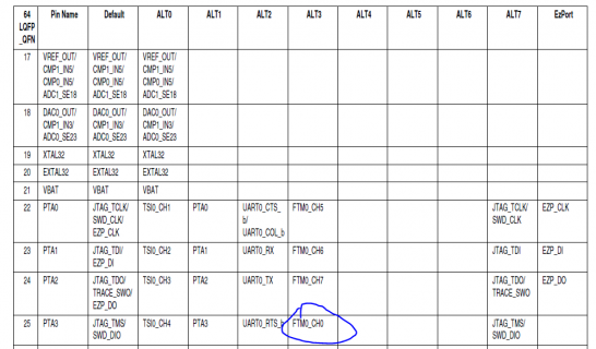
Here s a pic of the data sheet, where I got my pin MUX assignment.

Do you see any issues? I am new to this embedded programming so I don't really know how to properly troubleshoot. Any info, rules of thumb would be greatly appreciated.
I am using Arduino IDE.
But something isn't working.
I am basing my code off an edge aligned example from here
https://www.nxp.com/docs/en/application-note/AN5142.pdf
I read back the PORTA_PCR3 register and got 768 (dec)
Here s a pic of the data sheet, where I got my pin MUX assignment.

Do you see any issues? I am new to this embedded programming so I don't really know how to properly troubleshoot. Any info, rules of thumb would be greatly appreciated.
I am using Arduino IDE.
Code:
void setup() {
  // put your setup code here, to run once:
/* PORTs for FTM0 initialization */

  SIM_SCGC6|=0x03000000; //enable FTM0 and FTM0 module clock
  FTM0_CONF=0xC0; //set up BDM in 11
  FTM0_FMS=0x00; //clear the WPEN so that WPDIS is set in FTM0_MODE register
  FTM0_MODE|=0x05; //enable write the FTM CnV register
  FTM0_MOD=1000;
  FTM0_C0SC=0x28; //edge-alignment, PWM initial state is High, becomes low //after match
  FTM0_C1SC=0x28;
  FTM0_COMBINE=0x02; //complementary mode for CH0&CH1 of FTM0
  FTM0_COMBINE|=0x10; //dead timer insertion enabled in complementary mode for //CH0&CH1 of

  FTM0_C1V=500;
  FTM0_C0V=500;
  FTM0_C2SC=0x28;
  FTM0_C3SC=0x28;
  FTM0_COMBINE|=0x0200;
  FTM0_COMBINE|=0x1000;
  FTM0_DEADTIME=0x00;
  FTM0_C3V=250;
  FTM0_C2V=250;
  FTM0_CNTIN=0x00;
  FTM0_SC=0x08; //PWM edge_alignment, system clock driving, dividing by 1
  PORTA_PCR3 = PORT_PCR_MUX(3); // FTM0 CH0 - Pin 25
  Serial.begin(9600);
}

void loop() {
  // put your main code here, to run repeatedly:
  Serial.println(PORTA_PCR3);
  delay(1);
}
