How do i connect an SPI SSD1309 display to a T4.0?

Status
Not open for further replies.

Frukost

Well-known member
OK, so i want to connect a SPI SSD1309 display to my T4.0 board (data sheet here), and wanted to ask some things:

Apart from Vcc and GND, will it be enough to connect the displays SDA pin to MOSI (pin 11 on the T4.0), and SCL to SCK (pin 13 on the T4.0)?

Do i also need to connect the reset, data/command or chip select pins on the display? I don't seem to need those functions for my project. As for connecting the MISO pin (12), i intend to only send data to the display, and it's not obvious to me how i would connect it even if i needed to. Are these pins optional?

As for libraries, the u8g2, SparkFun HyperDisplay SSD1309, and also the SSD1306 libraries will work, unless i'm mistaken?
 
Last edited:
On page 13 of the datasheet, you can see this chip has 5 different configurations. How you connect it depends on which of those configurations is used.

As a practical matter, you almost certainly will buy a display with this chip built in. Pretty much only the companies who make the displays actually buy the chip. Everyone else buys the displays with the chip already connected.

In other words, to give you useful help, we really need to see which display you're using. The info about the chip inside the display leaves out importany details about how the chip is used inside the actual display you're buying.
 
Thanks for your reply, i see your point.

I looked into it some more, and found that the store from where i bought it refers to the U8G2_SSD1309_128X64_NONAME0_F_4W_SW_SPI constructor in the u8g2 library. Looking at https://github.com/olikraus/u8g2/wiki/u8g2setupcpp#constructor-name i found that 4W_SW_SPI means 4-wire (clock, data, cs and dc) software emulated SPI. I also found that the reset pin is optional, which leaves me to assume following connections:

Display - Teensy
SCK - SCK (pin 13)
SDA - MOSI (pin 11)
CS - CS (pin 10)
DC - ?

Does this mean that DC can be handled by any digital pin?

Also, according to this post i take it that hardware SPI is faster. If so, i intend to trying out the u8g2 library's equivalent for hardware SPI as well. According to olikraus the u8g2 hardware SPI code is based on the Arduino SPI library. Would that be compatible with the teensys hardware ISP?
 
the store from where i bought it

Maybe you could give us a link to the product page? Or show a photo of the display?

Please, try to imagine if you were reading this thread and trying to help. Why keep us guessing about what display you really have?
 
Maybe you could give us a link to the product page? Or show a photo of the display?

Please, try to imagine if you were reading this thread and trying to help. Why keep us guessing about what display you really have?

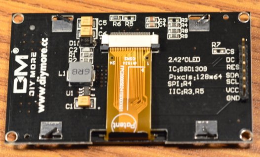
I provided a link to a photo of the display in my first post. The full page is (in swedish): https://pchbutik.se/display/1552-oled-display-242-tummed-128x64-vita-pixlar-spi-ssd1309.html. I should probably have mentioned that there isn't too much info to begin with, hence my questions.
 
Again I think, this is standard SPI...
So with standard SPI pins
SCk(13), SDA(11), CS and DC and maybe Reset(RES) more or less any digital IO pin.
CS (Chip select) often times pin 10...
DC (Data/Command) Often times pin 9 (or 8)
Res - often times can float, other times if display does not have a PU or PD resistor you may need to tie it to something like 3.3v or GND...

If there are specific pins that some library needs... probably depends on library
 
Ah, I didn't see the photo earlier.

Agreed, looks like normal SPI like all the other displays, except MISO isn't present.

I might have a similar display laying around in a pile of to-be-tested-someday hardware....
 
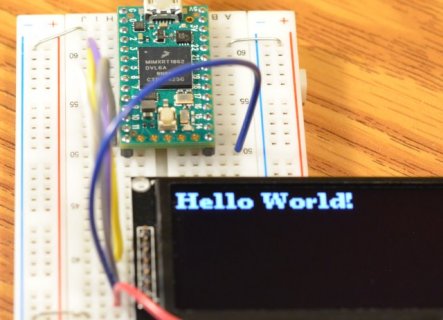
Found my SSD1309 display. It definitely works with Teensy 4.0 and u8g2.

a1.JPG

Here's the code I ran.

Code:
#include <Arduino.h>
#include <U8g2lib.h>
#include <SPI.h>
#include <Wire.h>

U8G2_SSD1309_128X64_NONAME0_F_4W_SW_SPI u8g2(U8G2_R0, /* clock=*/ 13, /* data=*/ 11, /* cs=*/ 10, /* dc=*/ 9, /* reset=*/ 8);

void setup(void) {
  u8g2.begin();
}

void loop(void) {
  u8g2.clearBuffer();					// clear the internal memory
  u8g2.setFont(u8g2_font_ncenB08_tr);	// choose a suitable font
  u8g2.drawStr(0,10,"Hello World!");	// write something to the internal memory
  u8g2.sendBuffer();					// transfer internal memory to the display
  delay(1000);  
}

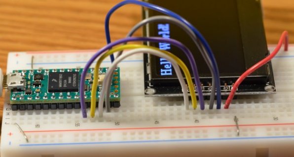
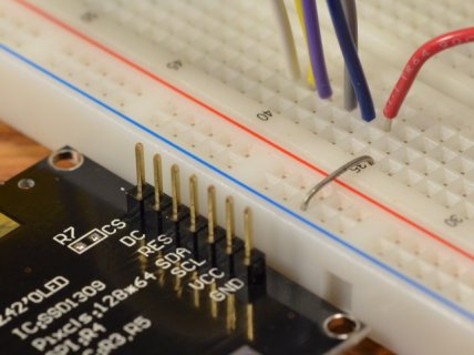
More photos so you can see exactly how I connected the wires. Hopefully this help you get the correct connection?

a2.JPG

a3.JPG

a4.JPG
 
Thanks, that's really helpful.

I see that you used the software spi constructor. I'll see if i can make the hardware equivalent work too.
 
OK, so everything is working fine now, thanks to your guidance!

The circuit is wired for software SPI, but codewise the hardware SPI constructor (U8G2_SSD1309_128X64_NONAME0_F_4W_HW_SPI u8g2(U8G2_R0, 10, 9); ) works as well.

Seeing as the hardware constructor only utilizes CS and DC, does this mean that i only need to wire those two pins? I'm asking to learn more about the differences between software and hardware SPI.
 
Status
Not open for further replies.
Back
Top