Hey everyone, I'm trying to build a volume mixer over serial for Windows and I'm having a bit of trouble planning out how to put everything together. I don't have a lot of electronics knowledge or experience so bear with me
The current plan is to use a Teensy 3.6 or 4.1, 8 push-button rotary encoders with a built-in RGB LED, possibly a few led push-buttons, and an LCD or OLED screen to show volume levels and other info. I don't have any of the components yet and I've just been playing around with a couple of regular encoders on an Arduino Nano.
My main concern is how to provide enough power to the LEDs since from what I can tell the Teensy can only output 10mA per pin at 3.3V but the datasheet says that they need 25mA at 2-2.4V for R and 3.3-3.7V for G/B. I'm not sure if I'm understanding the specs correctly but I will link the datasheet below. If the Teensy cannot provide sufficient power then my next plan would be to use a battery pack or some form of external power and transistors for each channel on each LED but I would like to avoid that because it almost seems like its just too much going on for what I'm trying to do.
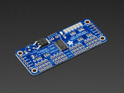
My next issue to tackle would be how to get all the components connected since the RGB encoders alone will need 48 pins. I would rather stick with the ~40 breadboard friendly pins since I don't feel to comfortable soldering anything to the pads so I will be looking into multiplexers but was hoping you guys could give me some general information. Is the I/O speed impacted in any way with multiple connections going to the same pins on the microcontroller? And which components would you recommend I connect to the multiplexer out of 16 encoder, 8 push button and 24 RGB pins? Or does it not matter at all?
Encoder: https://www.sparkfun.com/products/15141
Datasheet: http://cdn.sparkfun.com/datasheets/Components/Switches/EC12PLRGBSDVBF-D-25K-24-24C-6108-6HSPEC.pdf
I'm going to purchase them from a different website but I believe its the same product
If you guys have any other advice for me on how to make this project better, easier or more compact I would be happy to hear it
Thanks in advance


