Teensy 4.0 with HB01B0 camera

@yoknav

I see that also asked this question on Github. So will try to answer here.

First, the library does not support the 1-bit mode for data transfers. Second the link you provided will require some additional connections that don't seem to be there:
Capture.PNG
So you will probably have to solder on some additional wires or another header or....

As for the connections. We never tested with a T4 but it should work with the right combination of pins. The library uses FlexIO for controlling the IO so have to map Teensy pins to FlexIO pins (https://github.com/KurtE/FlexIO_t4) with that said this seems to run without giving pin configuration errors:

Code:
 * this sets the camera up using 4 bits only.
 *    HM01B0(uint8_t mclk_pin, uint8_t pclk_pin, uint8_t vsync_pin, uint8_t hsync_pin, en_pin,
 *    uint8_t g0, uint8_t g1,uint8_t g2, uint8_t g3,
 *    uint8_t g4=0xff, uint8_t g5=0xff,uint8_t g6=0xff,uint8_t g7=0xff, TwoWire &wire=Wire);
 */
HM01B0 hm01b0(6, 7, 8, 9, 2, 10, 12, 11, 13);

So the connections would be:
Code:
MCLK   =  6,
PCLK    =  7,
VSYNC  = 8,
HSYNC  = 9,
EN        = 2,
D0        = 10,
D1        = 12,
D2        = 11,
D3        =  13,
SDA      =  14
SCL       = 15

This should work but I am sure others will jump in if they see any errors with these pinouts.

Good luck and let us know how it works out.
 
Somewhere around my mess I think I have an Arducam camera. I ordered one that took a much longer time to deliver. Keep meaning to try it out.
The pins look correct, but would need to play with it to be sure.
 
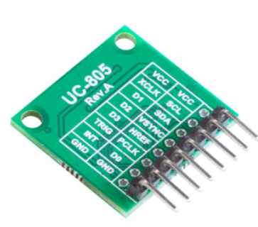
Thanks @mjs513! I soldered a pin header and connected as you suggested except SDA/SCL which is 18/19 on T4. There is no corresponding EN pin on the Arducam (hm01b0) so I did not use it. Since I am not using display and SD card, I have modified the HM01B0_ML_example.ino to keep it minimal for testing, just sending image to SerialUSB1. The Serial monitor shows logs below:


HM01B0 Camera Test
HM01B0_FLEXIO_CUSTOM_LIKE_4_BIT
------------------
SENSOR DETECTED :) MODEL HM01B0
OSC_CLK_DIV: 0x28
ImageSize (w,h): 324, 244


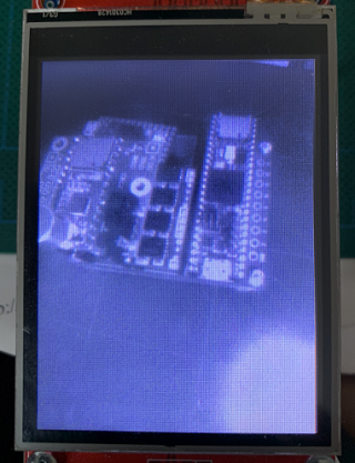
I opened the CameraVisualizerRawBytes.pde and it displays some unrecognizable garbled pattern. I played with the settings and the framerate=15 had a bit success and I was able to see grayscale image momentarily with rgb mess (see URL below) but it is not rendering correctly.

https://imgur.com/a/GMg5ywQ


Code:
#include <stdint.h>

#include <Wire.h>

#include "HM01B0.h"
#include "HM01B0_regs.h"
#include "constants.h"

void send_image( Stream *imgSerial);

// Library supports 8-bit or 4-bit camera interfacing to the Teensy Micromod Processor via pin selection
// or supports the default camera configuration.
PROGMEM const char hmConfig[][48] = {
  "HM01B0_SPARKFUN_ML_CARRIER",
  "HM01B0_FLEXIO_CUSTOM_LIKE_8_BIT",
  "HM01B0_FLEXIO_CUSTOM_LIKE_4_BIT"
};

#define _hmConfig 2 // select mode 

HM01B0 hm01b0(6, 7, 8, 9, 2, 10, 12, 11, 13);

// Configs frameBuffers for use with the camera
uint16_t FRAME_WIDTH, FRAME_HEIGHT;
uint8_t frameBuffer[(324) * 244];
uint8_t sendImageBuf[(324) * 244 * 2];

void setup()
{
  Serial.begin(921600);

  Serial.println("HM01B0 Camera Test");
  Serial.println( hmConfig[_hmConfig] );
  Serial.println("------------------");

  uint16_t ModelID;
  ModelID = hm01b0.get_modelid();
  if (ModelID == 0x01B0) {
    Serial.printf("SENSOR DETECTED :-) MODEL HM0%X\n", ModelID);
  } else {
    Serial.println("SENSOR NOT DETECTED! :-(");
    while (1) {}
  }

  uint8_t status;

  status = hm01b0.loadSettings(LOAD_DEFAULT_REGS);

  if (_hmConfig == 2) {
    status = hm01b0.set_framesize(FRAMESIZE_QVGA4BIT);
  } else {
    status = hm01b0.set_framesize(FRAMESIZE_QVGA);
  }

  if (status != 0) {
    Serial.println("Settings failed to load");
    while (1) {}
  }
  hm01b0.set_framerate(15);  //15, 30, 60
  hm01b0.set_gainceiling(GAINCEILING_2X);
  hm01b0.set_brightness(3);
  hm01b0.set_autoExposure(true, 1500);  //higher the setting the less saturaturation of whiteness
  hm01b0.cmdUpdate();  //only need after changing auto exposure settings
  hm01b0.set_mode(HIMAX_MODE_STREAMING, 0); // turn on, continuous streaming mode

  FRAME_HEIGHT = hm01b0.height();
  FRAME_WIDTH  = hm01b0.width();
  Serial.printf("ImageSize (w,h): %d, %d\n", FRAME_WIDTH, FRAME_HEIGHT);
}

void loop()
{
  send_image( &SerialUSB1 );
}

// Pass 8-bit (each) R,G,B, get back 16-bit packed color
uint16_t color565(uint8_t r, uint8_t g, uint8_t b) {
  return ((r & 0xF8) << 8) | ((g & 0xFC) << 3) | (b >> 3);
}


void send_image( Stream *imgSerial) {
  uint32_t imagesize;
  imagesize = (320 * 240 * 2);
  //hm01b0.set_vflip(true);
  memset(frameBuffer, 0, sizeof(frameBuffer));
  hm01b0.set_mode(HIMAX_MODE_STREAMING_NFRAMES, 1);
  hm01b0.readFrame(frameBuffer);

  uint32_t image_idx = 0;
  uint32_t frame_idx = 0;

  for (uint32_t row = 0; row < 240; row++) {
    for (uint32_t col = 0; col < 320; col++) {
      frame_idx = (324 * (row + 2)) + col + 2;
      uint16_t framePixel = color565(frameBuffer[frame_idx], frameBuffer[frame_idx], frameBuffer[frame_idx]);
      sendImageBuf[image_idx++] = (framePixel) & 0xFF;
      sendImageBuf[image_idx++] = (framePixel >> 8) & 0xFF;
    }
  }

  imgSerial->write(0xFF);
  imgSerial->write(0xAA);

  imgSerial->write((const uint8_t *)&bmp_header, sizeof(bmp_header));

  imgSerial->write(sendImageBuf, imagesize);

  imgSerial->write(0xBB);
  imgSerial->write(0xCC);
}
 
Last edited:
I have modified the Processing script to capture based on header. It seems image is OK now but it works only with frame rate = 15 and has a lot of flickering. I used same camera with RP2040 and it works fine. Maybe I will try to hookup a display to see if it is USB serial timing issue.
Below is Arducam regs initialization header file URL.
https://github.com/ArduCAM/RPI-Pico-Cam/blob/master/rp2040_hm01b0/arducam/hm01b0_init.h.

Fair warning with that pde script - that was an existing Processing sketch and to be honest didn't spend much time on debugging it and I don't think I had much luck with sending a continuous stream of images with it. Glad you got it working sort of.

Note: if you want to use the camera in video mode would suggest that you take a look at a couple of the other options in the example sketch that are setup to do video, continuous stream of images. With single frames you may be running into timing issues by just sending single frames to that sketch. The 2 options I am referring to are the 'F' and 'V' options.

On the to do list was to use the Arducam viewer (https://github.com/ArduCAM/Arduino/tree/master/ArduCAM/examples/host_app/ArduCAM_Host_V2.0_Windows) in video mode. With the existing sketch the option is available with dual serial to capture single frames with in conjunction with it.
 
@mjs513 Can you suggest alternative set of flexio pins for g0, g1, g2, g3? I wanted to connect a display(ILI9431) but SPI pins are occupied by them.
 
@mjs513 Can you suggest alternative set of flexio pins for g0, g1, g2, g3? I wanted to connect a display(ILI9431) but SPI pins are occupied by them.

I would take a look here: https://github.com/KurtE/FlexIO_t4. Shows the Teensy Pins to FlexIO pins that you can use. The criteria for the data pins are consecutive FlexIO pins.

So you could try using pins 2, 3, 4 and 33 for the data pins and then use 5,6,7 for the clock pins.
 
Code:
HM01B0 hm01b0(5, 6, 7, 8, 1,  2,  3,  4, 33);
These pins didn't work. The data pins are on FlexIO 1 and clk are using one pin from FlexIO_1 and 3 from FlexIO_2, I hope this is not the reason?
 
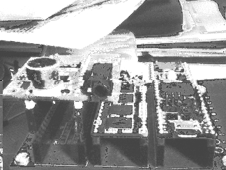
I was able to connect a display (ILI9431) using SPI (MOSI1/SCK1) pads on the back of T4. It has same issues. It works only with frame rate=15 with heavy tearing or flickering. Please see the gif below ('V' or 'F' both have similar output).
https://imgur.com/a/9jTBCZI

What settings should I play with to fix this?
 
I was able to connect a display (ILI9431) using SPI (MOSI1/SCK1) pads on the back of T4. It has same issues. It works only with frame rate=15 with heavy tearing or flickering. Please see the gif below.
https://imgur.com/a/9jTBCZI

What settings should I play with to fix this?

Just got on line and having coffee so it looks like we are quite a few hours apart.

Planning on soldering up the Arducam HM01B0 board today so I can play along. So I am assuming those pins I gave you are working or did you use a different set of pin?

Are you using your sketch or the ML-example sketch using the video options = 'F' or 'V'. Also there are some hints in the readme.

Would suggest that you try changing using the sparkfun configuration by adding this at the begining of your sketch:
Code:
#define USE_SPARKFUN 1
see if that helps. Their might be another option but I want to test it first.
 
Good morning @mjs513, we are 13 hours apart :). I have tried with/without USE_SPARKFUN but similar output. It only works with framerate=15 with screen tearing either cases. What are the other settings to investigate? BTW I'm using ML-example sketch using the video options = 'F' or 'V'. And pins are same as previous one:
Code:
HM01B0 hm01b0(6, 7, 8, 9, 3, 10, 12, 11, 13);
 
Good morning @mjs513, we are 13 hours apart :). I have tried with/without USE_SPARKFUN but similar output. It only works with framerate=15 with screen tearing either cases. What are the other settings to investigate?

In your previous sketch you are sending 1 image at a time in BMP format to USB. So I am assuming you are using something like this to send images to the display:
Code:
        Serial.println("Reading frame");
        memset((uint8_t*)frameBuffer, 0, sizeof(frameBuffer));
        hm01b0.readFrame(frameBuffer);
        Serial.println("Finished reading frame"); Serial.flush();
        tft.setOrigin(-2, -2);
[B]        tft.writeRect8BPP(0, 0, FRAME_WIDTH, FRAME_HEIGHT, frameBuffer, mono_palette);
[/B]        tft.setOrigin(0, 0);
which is the 'f' option in the ML-example.

But as I said you should try using the video options in the example to send to the display. You haven't really made it clear what sketch you are using or what options you are using. At this point not sure other options - can you post your whole sketch and I will try it later today and let you know.

One other possibility is to add use 30frames per second and add a small delay between frame outputs - just guessing here.
 
Here is the whole sketch:
Code:
#include <stdint.h>
#include <SD.h>
#include <SPI.h>

#include <Wire.h>

#include "HM01B0.h"
#include "HM01B0_regs.h"
#include "constants.h"

// Library supports 8-bit or 4-bit camera interfacing to the Teensy Micromod Processor via pin selection
// or supports the default camera configuration.
PROGMEM const char hmConfig[][48] = {
 "HM01B0_SPARKFUN_ML_CARRIER",    
 "HM01B0_FLEXIO_CUSTOM_LIKE_8_BIT",
 "HM01B0_FLEXIO_CUSTOM_LIKE_4_BIT"
};

#define _hmConfig 2 // select mode 

#if _hmConfig == 0
HM01B0 hm01b0(HM01B0_SPARKFUN_ML_CARRIER);

#elif _hmConfig == 1
/* We are doing manual settings: 
 * this one should duplicate the 8 bit ML Carrier:
 *    HM01B0(uint8_t mclk_pin, uint8_t pclk_pin, uint8_t vsync_pin, uint8_t hsync_pin, en_pin,
 *    uint8_t g0, uint8_t g1,uint8_t g2, uint8_t g3,
 *    uint8_t g4=0xff, uint8_t g5=0xff,uint8_t g6=0xff,uint8_t g7=0xff, TwoWire &wire=Wire); 
 */
HM01B0 hm01b0(7, 8, 33, 32, 2, 40, 41, 42, 43, 44, 45, 6, 9);

#elif _hmConfig == 2
/* We are doing manual settings: 
 * this sets the camera up using 4 bits only.
 *    HM01B0(uint8_t mclk_pin, uint8_t pclk_pin, uint8_t vsync_pin, uint8_t hsync_pin, en_pin,
 *    uint8_t g0, uint8_t g1,uint8_t g2, uint8_t g3,
 *    uint8_t g4=0xff, uint8_t g5=0xff,uint8_t g6=0xff,uint8_t g7=0xff, TwoWire &wire=Wire);
 */
//HM01B0 hm01b0(7, 8, 33, 32, 2, 40, 41, 42, 43);
HM01B0 hm01b0(6, 7, 8, 9, 3, 10, 12, 11, 13);

#endif

/*  Camera Configuration
 *  Two base configurations are used to initalize the camera.  The first is the Sparakfun configuration
 *  used in their library, the second is the configurations used by the OpenMV camera (modified) for the HM01B0
 *  If the define for USE_SPARKFUN is uncommented the sketch will use the Sparkfun configuration otherwise it will
 *  the OpenMV version which we modified slightly
 *  NOTE:
 *    1. If using 4 bit mode use set_framerate(60) with OpenMV config
 *    2. If using 8 bit/Sparkfun ML with the Sparkfun config use frameRate of 30. You do get flicker    
 *       using this combination.
 *    3. If using 8 bit/SparkfunML mode use set_framerate(60) with OpenMV config
 */
//#define USE_SPARKFUN 1

// If you want to use the SDCard to store images uncomment the following line
//#define USE_SDCARD 0
File file;

/* The sketch supports 2 displays: ST7789 and ILI9431 displays.  The ST7789 library is installed automatically
 * when you install Teensyduino.  For the ILI931 to work properly you will need to download and install the 
 * ILI9341_t3n library - https://github.com/KurtE/ILI9341_t3n
 * Select display by uncommenting the one you want and commenting out the other one.
 */
//#define TFT_ST7789 1
#define TFT_ILI9341 1

//#define TFT_DC  2   // "TX1" on left side of Sparkfun ML Carrier
//#define TFT_CS  0   // "D0" on right side of Sparkfun ML Carrier
//#define TFT_RST 4   // "RX1" on left side of Sparkfun ML Carrier
#define TFT_BL  5   // "D1" on right side of Sparkfun ML Carrier


#define TFT_DC  2
#define TFT_CS 0
#define TFT_RST 4
#define TFT_SCK 27
#define TFT_MISO 1
#define TFT_MOSI 26

#ifdef TFT_ST7789
//ST7735 Adafruit 320x240 display
#include <ST7789_t3.h>
ST7789_t3 tft = ST7789_t3(TFT_CS, TFT_DC, TFT_RST);
#define TFT_BLACK ST77XX_BLACK
#define TFT_YELLOW ST77XX_YELLOW
#define TFT_RED   ST77XX_RED
#define TFT_GREEN ST77XX_GREEN
#define TFT_BLUE  ST77XX_BLUE

#else
#include "ILI9341_t3n.h" // https://github.com/KurtE/ILI9341_t3n
//ILI9341_t3n tft = ILI9341_t3n(TFT_CS, TFT_DC, TFT_RST);
ILI9341_t3n tft = ILI9341_t3n(TFT_CS, TFT_DC, TFT_RST, TFT_MOSI, TFT_SCK, TFT_MISO);

#define TFT_BLACK ILI9341_BLACK
#define TFT_YELLOW ILI9341_YELLOW
#define TFT_RED   ILI9341_RED
#define TFT_GREEN ILI9341_GREEN
#define TFT_BLUE  ILI9341_BLUE
#endif

// Configs frameBuffers for use with the camera
uint16_t FRAME_WIDTH, FRAME_HEIGHT;
uint8_t frameBuffer[(324) * 244];
uint8_t sendImageBuf[(324) * 244 * 2];
uint8_t frameBuffer2[(324) * 244] DMAMEM;

//Sketch defines
bool g_continuous_flex_mode = false;
void * volatile g_new_flexio_data = nullptr;
uint32_t g_flexio_capture_count = 0;
uint32_t g_flexio_redraw_count = 0;
elapsedMillis g_flexio_runtime;
bool g_dma_mode = false;

ae_cfg_t aecfg;

void setup()
{
#ifdef TFT_ILI9341
  pinMode(TFT_BL, OUTPUT);
  digitalWrite(TFT_BL, HIGH);
  delay(100);
  tft.begin();
#else
  tft.init(240, 320);           // Init ST7789 320x240
#endif
  tft.setRotation(1);
  tft.fillScreen(TFT_RED);
  delay(500);
  tft.fillScreen(TFT_GREEN);
  delay(500);
  tft.fillScreen(TFT_BLUE);
  delay(500);
  tft.fillScreen(TFT_BLACK);
  delay(500);

  tft.fillScreen(TFT_BLACK);
  tft.setTextColor(TFT_YELLOW);
  tft.setTextSize(2);
  tft.println("Waiting for Arduino Serial Monitor...");

  Serial.begin(921600);
  
#if defined(USE_SDCARD)
  Serial.println("Using SDCARD - Initializing");
  if (!SD.begin(10)) {
    Serial.println("initialization failed!");
  }
  Serial.println("initialization done.");
  delay(100);
#endif

  Serial.println("HM01B0 Camera Test");
  Serial.println( hmConfig[_hmConfig] );
  Serial.println("------------------");

  tft.fillScreen(TFT_BLACK);

  uint16_t ModelID;
  ModelID = hm01b0.get_modelid();
  if (ModelID == 0x01B0) {
    Serial.printf("SENSOR DETECTED :-) MODEL HM0%X\n", ModelID);
  } else {
    Serial.println("SENSOR NOT DETECTED! :-(");
    while (1) {}
  }


  uint8_t status;
#if defined(USE_SPARKFUN)
  status = hm01b0.loadSettings(LOAD_SHM01B0INIT_REGS);  //hangs the TMM.
#else
  status = hm01b0.loadSettings(LOAD_DEFAULT_REGS);
#endif

  if(_hmConfig == 2){
    status = hm01b0.set_framesize(FRAMESIZE_QVGA4BIT);
  } else {
    status = hm01b0.set_framesize(FRAMESIZE_QVGA);
  }
  if (status != 0) {
    Serial.println("Settings failed to load");
    while (1) {}
  }
  hm01b0.set_framerate(15);  //15, 30, 60

  /* Gain Ceilling
   * GAINCEILING_1X
   * GAINCEILING_4X
   * GAINCEILING_8X
   * GAINCEILING_16X
   */
  hm01b0.set_gainceiling(GAINCEILING_2X);
  
  /* Brightness
   *  Can be 1, 2, or 3
   */
  hm01b0.set_brightness(3);
  hm01b0.set_autoExposure(true, 1500);  //higher the setting the less saturaturation of whiteness
  hm01b0.cmdUpdate();  //only need after changing auto exposure settings

  hm01b0.set_mode(HIMAX_MODE_STREAMING, 0); // turn on, continuous streaming mode

  FRAME_HEIGHT = hm01b0.height();
  FRAME_WIDTH  = hm01b0.width();
  Serial.printf("ImageSize (w,h): %d, %d\n", FRAME_WIDTH, FRAME_HEIGHT);

  showCommandList();
}

// Callbacks for frame buffers
bool hm01b0_flexio_callback(void *pfb)
{
  //Serial.println("Flexio callback");
  g_new_flexio_data = pfb;
  return true;
}
// Quick and Dirty
#define UPDATE_ON_CAMERA_FRAMES

uint8_t *pfb_last_frame_returned = nullptr;

bool hm01b0_flexio_callback_video(void *pfb)
{
  pfb_last_frame_returned = (uint8_t*)pfb;
#ifdef UPDATE_ON_CAMERA_FRAMES
  tft.setOrigin(-2, -2);
  if ((uint32_t)pfb_last_frame_returned >= 0x20200000u)
    arm_dcache_delete(pfb_last_frame_returned, FRAME_WIDTH*FRAME_HEIGHT);

  tft.writeRect8BPP(0, 0, FRAME_WIDTH, FRAME_HEIGHT, (uint8_t*)pfb_last_frame_returned, mono_palette);
  pfb_last_frame_returned = nullptr;
  tft.setOrigin(0, 0);
  uint16_t *pframebuf = tft.getFrameBuffer();
  if ((uint32_t)pframebuf >= 0x20200000u) arm_dcache_flush(pframebuf, FRAME_WIDTH*FRAME_HEIGHT);
#endif  
  //Serial.print("#");
  return true;
}

void frame_complete_cb() {
  //Serial.print("@");
#ifndef UPDATE_ON_CAMERA_FRAMES
  if (!pfb_last_frame_returned) return;
  tft.setOrigin(-2, -2);
  if ((uint32_t)pfb_last_frame_returned >= 0x20200000u)
    arm_dcache_delete(pfb_last_frame_returned, FRAME_WIDTH*FRAME_HEIGHT);

  tft.writeRect8BPP(0, 0, FRAME_WIDTH, FRAME_HEIGHT, (uint8_t*)pfb_last_frame_returned, mono_palette);
  pfb_last_frame_returned = nullptr;
  tft.setOrigin(0, 0);
  uint16_t *pfb = tft.getFrameBuffer();
  if ((uint32_t)pfb >= 0x20200000u) arm_dcache_flush(pfb, FRAME_WIDTH*FRAME_HEIGHT);
#endif
}


void loop()
{
  char ch;

  #if defined(USB_DUAL_SERIAL) || defined(USB_TRIPLE_SERIAL)
  while (SerialUSB1.available()) {
    ch = SerialUSB1.read();
    if ( 0x30 == ch ) {
      Serial.print(F("ACK CMD CAM start single shoot ... "));
      send_image( &SerialUSB1 );
      Serial.println(F("READY. END"));
    }
  }
  #endif
  if (Serial.available()) {
    ch = Serial.read();
    switch (ch) {
      case 'p':
      {
  #if defined(USB_DUAL_SERIAL) || defined(USB_TRIPLE_SERIAL)
        uint16_t pixel;
        memset((uint8_t*)frameBuffer, 0, sizeof(frameBuffer));
        hm01b0.readFrame(frameBuffer);
        uint32_t idx = 0;
        for (int i = 0; i < FRAME_HEIGHT * FRAME_WIDTH; i++) {
          idx = i * 2;
          pixel = color565(frameBuffer[i], frameBuffer[i], frameBuffer[i]);
          sendImageBuf[idx + 1] = (pixel >> 0) & 0xFF;
          sendImageBuf[idx] = (pixel >> 8) & 0xFF;
        }
        send_raw();
        Serial.println("Image Sent!");
        ch = ' ';
  #else
        Serial.println("*** Only works in USB Dual or Triple Serial Mode ***");
  #endif
        break;
      }
      case 'z':
      {
  #if defined(USE_SDCARD)
        save_image_SD();
  #endif
        break;
      }
      case 'b':
      {
  #if defined(USE_SDCARD)
        calAE();
        memset((uint8_t*)frameBuffer, 0, sizeof(frameBuffer));
        hm01b0.set_mode(HIMAX_MODE_STREAMING_NFRAMES, 1);
        hm01b0.readFrame(frameBuffer);
        save_image_SD();
        ch = ' '; 
  #endif
        break;
      }

      case 'f':
      {
        tft.useFrameBuffer(false);
        tft.fillScreen(TFT_BLACK);
        //calAE();
        Serial.println("Reading frame");
        memset((uint8_t*)frameBuffer, 0, sizeof(frameBuffer));
        hm01b0.readFrame(frameBuffer);
        Serial.println("Finished reading frame"); Serial.flush();
        tft.setOrigin(-2, -2);
        tft.writeRect8BPP(0, 0, FRAME_WIDTH, FRAME_HEIGHT, frameBuffer, mono_palette);
        tft.setOrigin(0, 0);
        ch = ' ';
        g_continuous_flex_mode = false;
        break;
      }
      case 'F':
      {
        if (!g_continuous_flex_mode) {
          if (hm01b0.readContinuous(&hm01b0_flexio_callback, frameBuffer, frameBuffer2)) {
            Serial.println("* continuous mode started");
            g_flexio_capture_count = 0;
            g_flexio_redraw_count = 0;
            g_continuous_flex_mode = true;
          } else {
            Serial.println("* error, could not start continuous mode");
          }
        } else {
          hm01b0.stopReadContinuous();
          g_continuous_flex_mode = false;
          Serial.println("* continuous mode stopped");
        }
        break;
      }
      case 'V':
      {
        if (!g_continuous_flex_mode) {
          if (hm01b0.readContinuous(&hm01b0_flexio_callback_video, frameBuffer, frameBuffer2)) {
            Serial.println("Before Set frame complete CB");
            if (!tft.useFrameBuffer(true)) Serial.println("Failed call to useFrameBuffer");
            tft.setFrameCompleteCB(&frame_complete_cb, false);
            Serial.println("Before UPdateScreen Async");
            tft.updateScreenAsync(true);
            Serial.println("* continuous mode (Video) started");
            g_flexio_capture_count = 0;
            g_flexio_redraw_count = 0;
            g_continuous_flex_mode = 2;
          } else {
            Serial.println("* error, could not start continuous mode");
          }
        } else {
          hm01b0.stopReadContinuous();
          tft.endUpdateAsync();
          g_continuous_flex_mode = 0;
          Serial.println("* continuous mode stopped");
        }
        ch = ' ';
        break;
      }
      case '1':
      {
        tft.fillScreen(TFT_BLACK);
        break;
      }
      case 0x30:
      {
          Serial.println(F("ACK CMD CAM start single shoot. END"));
          send_image( &Serial );
          Serial.println(F("READY. END"));
          break;
      }
      case '?':
      {
        showCommandList();
        ch = ' ';
        break;
      }
      default:
        break;
    }
   while (Serial.read() != -1); // lets strip the rest out
   }


  if ( g_continuous_flex_mode ) {
    if (g_new_flexio_data) {
      //Serial.println("new FlexIO data");
      if (1) {
      tft.setOrigin(-2, -2);
      tft.writeRect8BPP(0, 0, FRAME_WIDTH, FRAME_HEIGHT, (uint8_t *)g_new_flexio_data, mono_palette);
      tft.setOrigin(0, 0);
      tft.updateScreenAsync();
    }
      g_new_flexio_data = nullptr;
      g_flexio_redraw_count++;
      if (g_flexio_runtime > 10000) {
        // print some stats on actual speed, but not too much
        // printing too quickly to be considered "spew"
        //float redraw_rate = (float)g_flexio_redraw_count / (float)g_flexio_runtime * 1000.0f;
        g_flexio_runtime = 0;
        g_flexio_redraw_count = 0;
        //Serial.printf("redraw rate = %.2f Hz\t secs = %lu\t", redraw_rate, millis()/1000);
        //Serial.printf( "\tdeg  C=%u\n" , (uint32_t)tempmonGetTemp() );
      }
    }
  }
}

// Pass 8-bit (each) R,G,B, get back 16-bit packed color
uint16_t color565(uint8_t r, uint8_t g, uint8_t b) {
  return ((r & 0xF8) << 8) | ((g & 0xFC) << 3) | (b >> 3);
}


void send_image( Stream *imgSerial) {
  uint32_t imagesize;
  imagesize = (320 * 240 * 2);
  hm01b0.set_vflip(true);
  memset(frameBuffer, 0, sizeof(frameBuffer));
  hm01b0.set_mode(HIMAX_MODE_STREAMING_NFRAMES, 1);
  hm01b0.readFrame(frameBuffer);
  
  uint32_t image_idx = 0;
  uint32_t frame_idx = 0;

  for (uint32_t row = 0; row < 240; row++) {
    for (uint32_t col = 0; col < 320; col++) {
      frame_idx = (324 * (row + 2)) + col + 2;
      uint16_t framePixel = color565(frameBuffer[frame_idx], frameBuffer[frame_idx], frameBuffer[frame_idx]);
      sendImageBuf[image_idx++] = (framePixel) & 0xFF;
      sendImageBuf[image_idx++] = (framePixel >> 8) & 0xFF;
    }
  }
  
  imgSerial->write(0xFF);
  imgSerial->write(0xAA);

  imgSerial->write((const uint8_t *)&bmp_header, sizeof(bmp_header));

  imgSerial->write(sendImageBuf, imagesize);

  imgSerial->write(0xBB);
  imgSerial->write(0xCC);

  imgSerial->println(F("ACK CMD CAM Capture Done. END"));delay(50);

}

#if defined(USB_DUAL_SERIAL) || defined(USB_TRIPLE_SERIAL)
void send_raw() {
  uint32_t imagesize;
  imagesize = (FRAME_WIDTH * FRAME_HEIGHT * 2);
  SerialUSB1.write(sendImageBuf, imagesize); // set Tools > USB Type to "Dual Serial"
}
#endif

char name[] = "9px_0000.bmp";       // filename convention (will auto-increment)
  DMAMEM unsigned char img[3 * 320*240];
void save_image_SD() {
  uint8_t r, g, b;
  uint32_t x, y;

  Serial.print("Writing BMP to SD CARD File: ");

  // if name exists, create new filename, SD.exists(filename)
  for (int i = 0; i < 10000; i++) {
    name[4] = (i / 1000) % 10 + '0'; // thousands place
    name[5] = (i / 100) % 10 + '0'; // hundreds
    name[6] = (i / 10) % 10 + '0';  // tens
    name[7] = i % 10 + '0';         // ones
    if (!SD.exists(name)) {
      Serial.println(name);
      file = SD.open(name, FILE_WRITE);
      break;
    }
  }

  uint16_t w = FRAME_WIDTH;
  uint16_t h = FRAME_HEIGHT;

  //unsigned char *img = NULL;
  // set fileSize (used in bmp header)
  int rowSize = 4 * ((3 * w + 3) / 4);  // how many bytes in the row (used to create padding)
  int fileSize = 54 + h * rowSize;      // headers (54 bytes) + pixel data

//  img = (unsigned char *)malloc(3 * w * h);

  for (int i = 0; i < w; i++)
  {
    for (int j = 0; j < h; j++)
    {
      //r & 0xF8) << 8) | ((g & 0xFC) << 3) | (b >> 3
      x = i; y = (h - 1) - j;

      r = frameBuffer[(x + y * w)]    ;
      g = frameBuffer[(x + y * w)]    ;
      b = frameBuffer[(x + y * w)]    ;

      img[(x + y * w) * 3 + 2] = (unsigned char)(r);
      img[(x + y * w) * 3 + 1] = (unsigned char)(g);
      img[(x + y * w) * 3 + 0] = (unsigned char)(b);
    }
  }

  // create padding (based on the number of pixels in a row
  unsigned char bmpPad[rowSize - 3 * w];
  for (int i = 0; i < (int)(sizeof(bmpPad)); i++) {      // fill with 0s
    bmpPad[i] = 0;
  }

  unsigned char bmpFileHeader[14] = {'B', 'M', 0, 0, 0, 0, 0, 0, 0, 0, 54, 0, 0, 0};
  unsigned char bmpInfoHeader[40] = {40, 0, 0, 0, 0, 0, 0, 0, 0, 0, 0, 0, 1, 0, 24, 0};

  bmpFileHeader[ 2] = (unsigned char)(fileSize      );
  bmpFileHeader[ 3] = (unsigned char)(fileSize >>  8);
  bmpFileHeader[ 4] = (unsigned char)(fileSize >> 16);
  bmpFileHeader[ 5] = (unsigned char)(fileSize >> 24);

  bmpInfoHeader[ 4] = (unsigned char)(       w    );
  bmpInfoHeader[ 5] = (unsigned char)(       w >> 8);
  bmpInfoHeader[ 6] = (unsigned char)(       w >> 16);
  bmpInfoHeader[ 7] = (unsigned char)(       w >> 24);
  bmpInfoHeader[ 8] = (unsigned char)(       h    );
  bmpInfoHeader[ 9] = (unsigned char)(       h >> 8);
  bmpInfoHeader[10] = (unsigned char)(       h >> 16);
  bmpInfoHeader[11] = (unsigned char)(       h >> 24);

  // write the file (thanks forum!)
  file.write(bmpFileHeader, sizeof(bmpFileHeader));    // write file header
  file.write(bmpInfoHeader, sizeof(bmpInfoHeader));    // " info header

  for (int i = 0; i < h; i++) {                        // iterate image array
    file.write(img + (FRAME_WIDTH * (FRAME_HEIGHT - i - 1) * 3), 3 * FRAME_WIDTH);    // write px data
    file.write(bmpPad, (4 - (FRAME_WIDTH * 3) % 4) % 4);         // and padding as needed
  }
  //free(img);
  file.close();                                        // close file when done writing
  Serial.println("Done Writing BMP");
}

void showCommandList() {
  Serial.println("Send the 'f' character to read a frame using FlexIO (changes hardware setup!)");
  Serial.println("Send the 'F' to start/stop continuous using FlexIO (changes hardware setup!)");
  Serial.println("Send the 'V' character DMA to TFT async continuous  ...");
  Serial.println("Send the 'p' character to snapshot to PC on USB1");
  Serial.println("Send the 'b' character to save snapshot (BMP) to SD Card");
  Serial.println("Send the '1' character to blank the display");
  Serial.println("Send the 'z' character to send current screen BMP to SD");
  Serial.println();
}


void calAE() {
  // Calibrate Autoexposure
  Serial.println("Calibrating Auto Exposure...");
  memset((uint8_t*)frameBuffer, 0, sizeof(frameBuffer));
  if (hm01b0.cal_ae(10, frameBuffer, FRAME_WIDTH * FRAME_HEIGHT, &aecfg) != HM01B0_ERR_OK) {
    Serial.println("\tnot converged");
  } else {
    Serial.println("\tconverged!");
    hm01b0.cmdUpdate();
  }
}
 
So thats pretty much the ML_example sketch using your pin configs. Wasn't sure.

What option are you getting the tearing with?

EDIT: Ok cross posted - will check it later today
 
@mjs513 Something interesting I discovered accidentally! If MCLK is not connected to the Arducam (XCLK pin), it works well with all frame rates.There are tearing when moving fast in 'V' mode and somewhat negligible tearing in 'F' mode with fast movement but slow movement images are quite smooth. If we fix the MCLK clock, I think rest of the tearing will be gone.
 
@mjs513 Something interesting I discovered accidentally! If MCLK is not connected to the Arducam (XCLK pin), it works well with all frame rates.There are tearing when moving fast in 'V' mode and somewhat negligible tearing in 'F' mode with fast movement but slow movement images are quite smooth. If we fix the MCLK clock, I think rest of the tearing will be gone.

Thanks for the find - one thing that I didn't check before this was a comparision of the pins between the TMM camera and the Arducam. Again great find. Ps - in between home related projects so will definitely play later.
 
@yokonav

I did get a chance yesterday to test the Arducam out, but I was using a T4.1 - only because it was easier to hook wires up to it on a breadboard. ILI9341 on SPI1 and the camera using the same pinouts. Was not happy with the results.

Camera on Micromod: Image_20210729_134140.png and Arducam on the T4.1: 9px_0002.png

Hard to see from the pictures but the image from the Micromod is actually better and less fuzzy. Did try a couple of things:
1. Used the Arducam Initialization Registers and no change. Comparing them to the default initialization they look to be exactly the same.
2. Tried a few different settings with no luck - just made it worse or no change.

Wondering now if the Arducam actually supports 4-bit mode based on other images I looked at. Going to play some more today and will amend post as necessary.
 
Morning, @mjs513 - I will try to play today as well. Been busy with some other things. You would think that they would both work the same, but could be wrong.

might help to see your settings. (i.e. which pins), to see if I notice anything

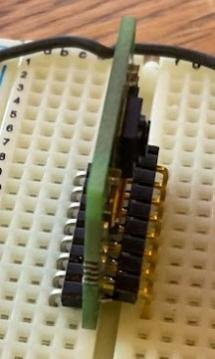
As I mentioned on a different channel, I did solder up my camera with 2nd row to make it easy to connect on Breadboard:
screenshot.jpg

What I need to remember is how we mapped from FlexIO pins to image. That is if we did some masking and shifting, or if we needed the 4 bits to be in contiguous FlexIO pin order and we pass off the starting pin number to the FlexIO system..

Need more coffee before...
 
Good Morning @KurtE :)

Just pushed the minor changes I made to the library so you can specify the enable pin as 255 and added the arducam res settings just as a test. Here is the sketch I am using:


EDIT: Forgot I did add an option 3 so you can config for the PJRC Breakout:
Code:
#elif _hmConfig == 3
HM01B0 hm01b0(HM01B0_PJRC_CARRIER);
 

Attachments

  • HM01B0_t4_example-210730a.zip
    6.6 KB · Views: 64
I've been trying to get the HM01B0 working in SINGLE FRAME CAPTURE mode over the 1-bit interface on a Teensy 3.6. More or less trying to code it up from scratch based on the datasheet, and I'm not getting good results. Before I commit a bunch of time to this, I wanted to see what the pros here @KurtE and @mjs513 think. I'm not sure I fully understand the FlexIO element here and how important that is to getting this working. Wondering if it is even possible to capture SINGLE frames with my more naive approach using digitalRead or digitalReadFast. Is it possible the clock on this camera is too fast?

To start, I'm just trying to generate a test pattern (solid RGB Color Bar) and read out a few rows and print that to the Serial monitor in raw form.

The code looks something like this, for the readSingleFrame bit. Of course there is a bunch of setup. Please feel free to tear my code to bits :p

Code:
    while(digitalReadFast(PIN_VSYNC) == LOW) { }
    while(digitalReadFast(PIN_VSYNC) == HIGH)
    {
          while(digitalReadFast(PIN_HREF) == false && digitalReadFast(PIN_VSYNC) == HIGH) { }
          VSYNC_count++;
    
          //Read a row
          while(digitalReadFast(PIN_HREF) == true) 
          { 
              HREF_count++;
              while(digitalReadFast(PIN_PCLCK) == false) { }
              
              if (bit_position >= 7) {bit_position = 0; byte_position++;}
              new_bit = 0; bitWrite(new_bit, bit_position, digitalReadFast(PIN_DATA));
              frameBuffer[byte_position] = frameBuffer[byte_position] | new_bit;
              bit_position++;
                
              while(digitalReadFast(PIN_PCLCK) == true) { }
          }
          
    }


    for (int i = 0; i < frameBufferSize; i++)
    {
      Serial.println(frameBuffer[i]);
    }
My reason for not wanting to specifically use the FlexIO is that I'd really like to port this over to a nrF5280 chip with BLE later on. It's not ideal, I know, but I often try to get things working with a Teensy and then see how feasible "downgrading" might be.
 
Back
Top