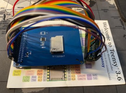
Questions about ILI9341 (16bit) with XPT2046 (touch) module on Teensy 3.6

Status
Not open for further replies.

SuperLocrian

Active member
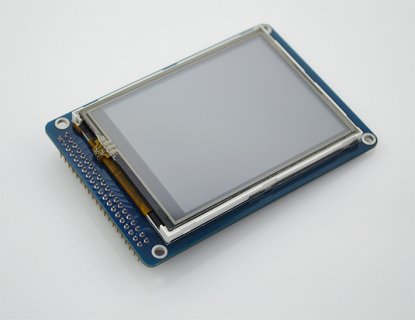
Recently I just found a Teensy 3.6 I bought years ago. And I had a thought to use it to control a touchable TFT screen. So I bought an ILI9341 (16bit) with XPT2046 (touch) module, which looks like this:
TB2rZOpXVXXXXaQXXXXXXXXXXXX-39773402.jpg
It's embarrassing that I could not found any library for it (none for 16bit) and no examples or demos. I am a newbie here. Could you help me with it?
Additionally, I uploaded all the materials I have. Plz, see the attachments. Thx a lot. :)
View attachment XPT2046datasheet.pdfView attachment TJC-9341-032.pdfView attachment schematic diagram.pdf
 
There are libraries for both ILI9341_t3 and XTP2045_Touchscreen in Teensyduino.
Look at directory C:\Program Files x86\Arduino\hardware\teensy\avr\libraries
 
Thanks for your reply. Actually, I have seen ILI9341_t3, but I can't find anything about this 16bit TFT, which has 40 pins
 
Sorry, I have not played at all with any of the ILI9341 displays that did not use SPI to communicate. And as such I don't know of any libraries that are setup to do the 16 bit transfers.
Hope someone else has.

Good luck
 
Sorry, I have not played at all with any of the ILI9341 displays that did not use SPI to communicate. And as such I don't know of any libraries that are setup to do the 16 bit transfers.
Hope someone else has.

Good luck

Thank you KurtE for your reply. I could not find any 16-bit transfers demos indeed.
 
You do not state what size etc the display is. It might be useful to show a photo of the reverse of the display. Sometimes they can be setup for various interface types.
 
There is some info discussed here.
Someone else had the same problem.
UTFT is in C:\Program Files (x86)\Arduino\hardware\teensy\avr\libraries\UTFT
 
You will also need to create your ILI8341_16 from ILI9327 as described in this which I pointed you towards earlier.
 
Modified UTFT_Demo_320x240 as below to simulate a 16bit parallel connection as below
Code:
UTFT myGLCD(ILI9327, RS, WR, CS, RST);  // Remember to change the model parameter to suit your display module!
Set up HW_Teensy3.h as below
Code:
// SET WHICH PIN DEFINITIONS TO USE HERE
// (only uncomment 1 of these 3 lines)
//
//#define PORTS  USE_B_D_PORTS
//#define PORTS  USE_C_D_PORTS
#define PORTS  USE_USER_PORTS

Without a display connected, and set up for a ILI9327 16 bit display it compiles and links ok on my system!

That causes UTFT to do bit-banging to drive the display with the connections as per HW_Teensy3.h.

Further investigation is required to see if 16bit IO direct from the ports on a 1.36 can be attained.
 
Modified UTFT_Demo_320x240 as below to simulate a 16bit parallel connection as below
Code:
UTFT myGLCD(ILI9327, RS, WR, CS, RST);  // Remember to change the model parameter to suit your display module!
Set up HW_Teensy3.h as below
Code:
// SET WHICH PIN DEFINITIONS TO USE HERE
// (only uncomment 1 of these 3 lines)
//
//#define PORTS  USE_B_D_PORTS
//#define PORTS  USE_C_D_PORTS
#define PORTS  USE_USER_PORTS
That causes UTFT to do bit-banging to drive the display with the connections as per HW_Teensy3.h.

Further investigation is required to see if 16bit IO direct from the ports on a 1.36 can be attained.

Thank you! I will dig into it tomorrow. But it seems my screen is a little bit out-of-date right now.
 
Modified UTFT_Demo_320x240 as below to simulate a 16bit parallel connection as below
Code:
UTFT myGLCD(ILI9327, RS, WR, CS, RST);  // Remember to change the model parameter to suit your display module!
Set up HW_Teensy3.h as below
Code:
// SET WHICH PIN DEFINITIONS TO USE HERE
// (only uncomment 1 of these 3 lines)
//
//#define PORTS  USE_B_D_PORTS
//#define PORTS  USE_C_D_PORTS
#define PORTS  USE_USER_PORTS

Without a display connected, and set up for a ILI9327 16 bit display it compiles and links ok on my system!

That causes UTFT to do bit-banging to drive the display with the connections as per HW_Teensy3.h.

Further investigation is required to see if 16bit IO direct from the ports on a 1.36 can be attained.

I modified the HW_Teensy3.h as you told but still get the same error " #error "Unsupported ARM MCU!" Error compiling for board Teensy 3.6. "

I think it should have something to do with the following definition in UTFT.cpp:
Code:
#elif defined(__arm__)
	#include "hardware/arm/HW_ARM.h"
	#if defined(__SAM3X8E__)
		#pragma message("Compiling for Arduino Due (AT91SAM3X8E)...")
		#include "hardware/arm/HW_SAM3X8E.h"
	#elif defined(__MK20DX128__) || defined(__MK20DX256__) || defined(__MK64FX512__) || defined(__MK66FX1M0__)
		#pragma message("Compiling for Teensy 3.X...")
		#include "hardware/arm/HW_Teensy3.h"
	#else
		#error "Unsupported ARM MCU!"
	#endif
#endif
 
Modified UTFT_Demo_320x240 as below to simulate a 16bit parallel connection as below
Code:
UTFT myGLCD(ILI9327, RS, WR, CS, RST);  // Remember to change the model parameter to suit your display module!
Set up HW_Teensy3.h as below
Code:
// SET WHICH PIN DEFINITIONS TO USE HERE
// (only uncomment 1 of these 3 lines)
//
//#define PORTS  USE_B_D_PORTS
//#define PORTS  USE_C_D_PORTS
#define PORTS  USE_USER_PORTS

Without a display connected, and set up for a ILI9327 16 bit display it compiles and links ok on my system!

That causes UTFT to do bit-banging to drive the display with the connections as per HW_Teensy3.h.

Further investigation is required to see if 16bit IO direct from the ports on a 1.36 can be attained.

I updated the UTFT library, modified the HW_Teensy3.h and the UTFT_Demo_320x240. The verification has passed. But I am still looking for the pins connection method between the Teensy 3.6 and the 16bit ili9341 XPT2046. module. I connected as following:
Code:
// Teensy 3.x TFT Test Board                   : <display model>,23,22, 3, 4
But I still can't get any info about the data connection and surely nothing on the screen.
 
Last edited:
You will also need to create your ILI8341_16 from ILI9327 as described in this which I pointed you towards earlier.

I now wired the port 0-15 of teensy 3.6 to the DB0 - DB15 of the screen module. RS - 36, WR - 35, CS - 34, RST - 33, VCC - 3.3v, GND - GND, LED-A - 3.3v. And then I run the UTFT_Demo_320x240, whose code is here:
Code:
// UTFT_Demo_320x240 
// Copyright (C)2015 Rinky-Dink Electronics, Henning Karlsen. All right reserved
// web: http://www.RinkyDinkElectronics.com/
//
// This program is a demo of how to use most of the functions
// of the library with a supported display modules.
//
// This demo was made for modules with a screen resolution 
// of 320x240 pixels.
//
// This program requires the UTFT library.
//

#include <UTFT.h>

// Declare which fonts we will be using
extern uint8_t SmallFont[];

// Set the pins to the correct ones for your development shield
// ------------------------------------------------------------
// Standard Arduino Mega/Due shield            : <display model>,38,39,40,41
// CTE TFT LCD/SD Shield for Arduino Due       : <display model>,25,26,27,28
// Teensy 3.x TFT Test Board                   : <display model>,23,22, 3, 4
// ElecHouse TFT LCD/SD Shield for Arduino Due : <display model>,22,23,31,33
//
// Remember to change the model parameter to suit your display module!
UTFT myGLCD(ILI9327,36,35,34,33);

void setup()
{
  randomSeed(analogRead(0));
  
// Setup the LCD
  myGLCD.InitLCD();
  myGLCD.setFont(SmallFont);
}

void loop()
{
  int buf[318];
  int x, x2;
  int y, y2;
  int r;

// Clear the screen and draw the frame
  myGLCD.clrScr();

  myGLCD.setColor(255, 0, 0);
  myGLCD.fillRect(0, 0, 319, 13);
  myGLCD.setColor(64, 64, 64);
  myGLCD.fillRect(0, 226, 319, 239);
  myGLCD.setColor(255, 255, 255);
  myGLCD.setBackColor(255, 0, 0);
  myGLCD.print("* Universal Color TFT Display Library *", CENTER, 1);
  myGLCD.setBackColor(64, 64, 64);
  myGLCD.setColor(255,255,0);
  myGLCD.print("<http://www.RinkyDinkElectronics.com/>", CENTER, 227);

  myGLCD.setColor(0, 0, 255);
  myGLCD.drawRect(0, 14, 319, 225);

// Draw crosshairs
  myGLCD.setColor(0, 0, 255);
  myGLCD.setBackColor(0, 0, 0);
  myGLCD.drawLine(159, 15, 159, 224);
  myGLCD.drawLine(1, 119, 318, 119);
  for (int i=9; i<310; i+=10)
    myGLCD.drawLine(i, 117, i, 121);
  for (int i=19; i<220; i+=10)
    myGLCD.drawLine(157, i, 161, i);

// Draw sin-, cos- and tan-lines  
  myGLCD.setColor(0,255,255);
  myGLCD.print("Sin", 5, 15);
  for (int i=1; i<318; i++)
  {
    myGLCD.drawPixel(i,119+(sin(((i*1.13)*3.14)/180)*95));
  }
  
  myGLCD.setColor(255,0,0);
  myGLCD.print("Cos", 5, 27);
  for (int i=1; i<318; i++)
  {
    myGLCD.drawPixel(i,119+(cos(((i*1.13)*3.14)/180)*95));
  }

  myGLCD.setColor(255,255,0);
  myGLCD.print("Tan", 5, 39);
  for (int i=1; i<318; i++)
  {
    myGLCD.drawPixel(i,119+(tan(((i*1.13)*3.14)/180)));
  }

  delay(2000);

  myGLCD.setColor(0,0,0);
  myGLCD.fillRect(1,15,318,224);
  myGLCD.setColor(0, 0, 255);
  myGLCD.setBackColor(0, 0, 0);
  myGLCD.drawLine(159, 15, 159, 224);
  myGLCD.drawLine(1, 119, 318, 119);

// Draw a moving sinewave
  x=1;
  for (int i=1; i<(318*20); i++) 
  {
    x++;
    if (x==319)
      x=1;
    if (i>319)
    {
      if ((x==159)||(buf[x-1]==119))
        myGLCD.setColor(0,0,255);
      else
        myGLCD.setColor(0,0,0);
      myGLCD.drawPixel(x,buf[x-1]);
    }
    myGLCD.setColor(0,255,255);
    y=119+(sin(((i*1.1)*3.14)/180)*(90-(i / 100)));
    myGLCD.drawPixel(x,y);
    buf[x-1]=y;
  }

  delay(2000);
  
  myGLCD.setColor(0,0,0);
  myGLCD.fillRect(1,15,318,224);

// Draw some filled rectangles
  for (int i=1; i<6; i++)
  {
    switch (i)
    {
      case 1:
        myGLCD.setColor(255,0,255);
        break;
      case 2:
        myGLCD.setColor(255,0,0);
        break;
      case 3:
        myGLCD.setColor(0,255,0);
        break;
      case 4:
        myGLCD.setColor(0,0,255);
        break;
      case 5:
        myGLCD.setColor(255,255,0);
        break;
    }
    myGLCD.fillRect(70+(i*20), 30+(i*20), 130+(i*20), 90+(i*20));
  }

  delay(2000);
  
  myGLCD.setColor(0,0,0);
  myGLCD.fillRect(1,15,318,224);

// Draw some filled, rounded rectangles
  for (int i=1; i<6; i++)
  {
    switch (i)
    {
      case 1:
        myGLCD.setColor(255,0,255);
        break;
      case 2:
        myGLCD.setColor(255,0,0);
        break;
      case 3:
        myGLCD.setColor(0,255,0);
        break;
      case 4:
        myGLCD.setColor(0,0,255);
        break;
      case 5:
        myGLCD.setColor(255,255,0);
        break;
    }
    myGLCD.fillRoundRect(190-(i*20), 30+(i*20), 250-(i*20), 90+(i*20));
  }
  
  delay(2000);
  
  myGLCD.setColor(0,0,0);
  myGLCD.fillRect(1,15,318,224);

// Draw some filled circles
  for (int i=1; i<6; i++)
  {
    switch (i)
    {
      case 1:
        myGLCD.setColor(255,0,255);
        break;
      case 2:
        myGLCD.setColor(255,0,0);
        break;
      case 3:
        myGLCD.setColor(0,255,0);
        break;
      case 4:
        myGLCD.setColor(0,0,255);
        break;
      case 5:
        myGLCD.setColor(255,255,0);
        break;
    }
    myGLCD.fillCircle(100+(i*20),60+(i*20), 30);
  }
  
  delay(2000);
  
  myGLCD.setColor(0,0,0);
  myGLCD.fillRect(1,15,318,224);

// Draw some lines in a pattern
  myGLCD.setColor (255,0,0);
  for (int i=15; i<224; i+=5)
  {
    myGLCD.drawLine(1, i, (i*1.44)-10, 224);
  }
  myGLCD.setColor (255,0,0);
  for (int i=224; i>15; i-=5)
  {
    myGLCD.drawLine(318, i, (i*1.44)-11, 15);
  }
  myGLCD.setColor (0,255,255);
  for (int i=224; i>15; i-=5)
  {
    myGLCD.drawLine(1, i, 331-(i*1.44), 15);
  }
  myGLCD.setColor (0,255,255);
  for (int i=15; i<224; i+=5)
  {
    myGLCD.drawLine(318, i, 330-(i*1.44), 224);
  }
  
  delay(2000);
  
  myGLCD.setColor(0,0,0);
  myGLCD.fillRect(1,15,318,224);

// Draw some random circles
  for (int i=0; i<100; i++)
  {
    myGLCD.setColor(random(255), random(255), random(255));
    x=32+random(256);
    y=45+random(146);
    r=random(30);
    myGLCD.drawCircle(x, y, r);
  }

  delay(2000);
  
  myGLCD.setColor(0,0,0);
  myGLCD.fillRect(1,15,318,224);

// Draw some random rectangles
  for (int i=0; i<100; i++)
  {
    myGLCD.setColor(random(255), random(255), random(255));
    x=2+random(316);
    y=16+random(207);
    x2=2+random(316);
    y2=16+random(207);
    myGLCD.drawRect(x, y, x2, y2);
  }

  delay(2000);
  
  myGLCD.setColor(0,0,0);
  myGLCD.fillRect(1,15,318,224);

// Draw some random rounded rectangles
  for (int i=0; i<100; i++)
  {
    myGLCD.setColor(random(255), random(255), random(255));
    x=2+random(316);
    y=16+random(207);
    x2=2+random(316);
    y2=16+random(207);
    myGLCD.drawRoundRect(x, y, x2, y2);
  }

  delay(2000);
  
  myGLCD.setColor(0,0,0);
  myGLCD.fillRect(1,15,318,224);

  for (int i=0; i<100; i++)
  {
    myGLCD.setColor(random(255), random(255), random(255));
    x=2+random(316);
    y=16+random(209);
    x2=2+random(316);
    y2=16+random(209);
    myGLCD.drawLine(x, y, x2, y2);
  }

  delay(2000);
  
  myGLCD.setColor(0,0,0);
  myGLCD.fillRect(1,15,318,224);

  for (int i=0; i<10000; i++)
  {
    myGLCD.setColor(random(255), random(255), random(255));
    myGLCD.drawPixel(2+random(316), 16+random(209));
  }

  delay(2000);

  myGLCD.fillScr(0, 0, 255);
  myGLCD.setColor(255, 0, 0);
  myGLCD.fillRoundRect(80, 70, 239, 169);
  
  myGLCD.setColor(255, 255, 255);
  myGLCD.setBackColor(255, 0, 0);
  myGLCD.print("That's it!", CENTER, 93);
  myGLCD.print("Restarting in a", CENTER, 119);
  myGLCD.print("few seconds...", CENTER, 132);
  
  myGLCD.setColor(0, 255, 0);
  myGLCD.setBackColor(0, 0, 255);
  myGLCD.print("Runtime: (msecs)", CENTER, 210);
  myGLCD.printNumI(millis(), CENTER, 225);
  
  delay (10000);
}
But nothing comes out... I think it should have something to do with the ILI9327. I went through the URL you gave me. But I found they said there is an ILI9341_16 in the UTFT h file. But I can't find it. (PS. I have updated the library to the newest version). Thanks
 
I got stucked the whole day... I even reinstall the Teensyarduino and the UTFT library. The built-in UTFT library could compile for Teensy 3.6 but the screen is not working after I wired as guided as Example/UTFT/Teensy3/UTFT_Demo_320x240:
Code:
#include <UTFT.h>

// Declare which fonts we will be using
extern uint8_t SmallFont[];

// For 8 bit mode, these connections are required
//  LCD    Teensy3
//  ---    -------
//  DB8       2
//  DB9      14
//  DB10      7
//  DB11      8
//  DB12      6
//  DB13     20
//  DB14     21
//  DB15      5

// For 16 bit mode, these connections are *also* required
//  LCD    Teensy3
//  ---    -------
//  DB0      16
//  DB1      17
//  DB2      19
//  DB3      18
//  DB4       0
//  DB5       1
//  DB6      32  (bottom side)
//  DB7      25  (bottom side)

// These 4 signals can connect to any unused digital pins
#define RS  23
#define WR  22
#define CS  3
#define RST 4

UTFT myGLCD(ITDB28, RS, WR, CS, RST);  // Remember to change the model parameter to suit your display module!
Besides, when I include the lasted version of UTFT from the Rinky-Dink official website, it could not compile for Teensy 3.6...
Plz, could I get any help...
 
But nothing comes out... I think it should have something to do with the ILI9327. I went through the URL you gave me. But I found they said there is an ILI9341_16 in the UTFT h file. But I can't find it. (PS. I have updated the library to the newest version). Thanks
The documentation I pointed you towards indicated that you have to create your own ILI9341_16 yourself. The information presented in that documentation suggested how to do it.
It might be a good time to put up a photo of your teensy/display connections.
 
The documentation I pointed you towards indicated that you have to create your own ILI9341_16 yourself. The information presented in that documentation suggested how to do it.
It might be a good time to put up a photo of your teensy/display connections.

Thank you! Actually, I have wired them several times today. Now it has been wired as the guide in the built-in UTFT library (v2.72). Please see below.
connection.jpg

Code:
#include <UTFT.h>

// Declare which fonts we will be using

//  LCD    Teensy3
//  ---    -------
//  DB8       2
//  DB9      14
//  DB10      7
//  DB11      8
//  DB12      6
//  DB13     20
//  DB14     21
//  DB15      5

// For 16 bit mode, these connections are *also* required
//  LCD    Teensy3
//  ---    -------
//  DB0      16
//  DB1      17
//  DB2      19
//  DB3      18
//  DB4       0
//  DB5       1
//  DB6      32  (bottom side)
//  DB7      25  (bottom side)

// These 4 signals can connect to any unused digital pins
#define RS  23
#define WR  22
#define CS  3
#define RST 4
 
The documentation I pointed you towards indicated that you have to create your own ILI9341_16 yourself. The information presented in that documentation suggested how to do it.
It might be a good time to put up a photo of your teensy/display connections.

I read the discussion in that link. But I am confused about which version should I modify. I could only access v2.72 and v2.83.
 
Status
Not open for further replies.
Back
Top