Questions about ILI9341 (16bit) with XPT2046 (touch) module on Teensy 3.6

Status
Not open for further replies.
If you define your ports as USE_USER_PORTS then you wire up the wires as defined in that part for the USE_USER_PORTS as shown below.
That is the setup for USE_USER_PORTS which you van change just by changing the definitions. Ie if you want to use pin 21 instead of pin 15 then
Code:
#define DB_15 15
becomes
Code:
#define DB_15 21
All this is in HW_Teensy3.h
Code:
// SET WHICH PIN DEFINITIONS TO USE HERE
// (only uncomment 1 of these 3 lines)
//
//#define PORTS  USE_B_D_PORTS
//#define PORTS  USE_C_D_PORTS
#define PORTS  USE_USER_PORTS

#if (PORTS == USE_USER_PORTS)
	#pragma message("Using user-defined pins")
	#define DB_0 0
	#define DB_1 1
	#define DB_2 2
	#define DB_3 3
	#define DB_4 4
	#define DB_5 5
	#define DB_6 6
	#define DB_7 7
	#define DB_8 8
	#define DB_9 9
	#define DB_10 10
	#define DB_11 11
	#define DB_12 12
	#define DB_13 13
	#define DB_14 14
	#define DB_15 15
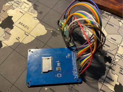
Bye the way your photo is useless for anyone trying to check your connections.
 
If you define your ports as USE_USER_PORTS then you wire up the wires as defined in that part for the USE_USER_PORTS as shown below.
That is the setup for USE_USER_PORTS which you van change just by changing the definitions. Ie if you want to use pin 21 instead of pin 15 then
Code:
#define DB_15 15
becomes
Code:
#define DB_15 21
All this is in HW_Teensy3.h
Code:
// SET WHICH PIN DEFINITIONS TO USE HERE
// (only uncomment 1 of these 3 lines)
//
//#define PORTS  USE_B_D_PORTS
//#define PORTS  USE_C_D_PORTS
#define PORTS  USE_USER_PORTS

#if (PORTS == USE_USER_PORTS)
	#pragma message("Using user-defined pins")
	#define DB_0 0
	#define DB_1 1
	#define DB_2 2
	#define DB_3 3
	#define DB_4 4
	#define DB_5 5
	#define DB_6 6
	#define DB_7 7
	#define DB_8 8
	#define DB_9 9
	#define DB_10 10
	#define DB_11 11
	#define DB_12 12
	#define DB_13 13
	#define DB_14 14
	#define DB_15 15
Bye the way your photo is useless for anyone trying to check your connections.

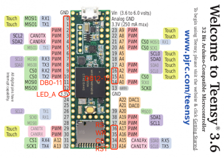
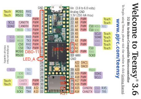
Understood. Emm... It's a little bit hard to take a clear photo of them. Maybe I can use this:
Connections.png
And now I go to reinstall the Teensyarduino, get back the UTFT v2.72, and modify the HW_Teensy3.h as:
Code:
// SET WHICH PIN DEFINITIONS TO USE HERE
// (only uncomment 1 of these 3 lines)
//
//#define PORTS  USE_B_D_PORTS
//#define PORTS  USE_C_D_PORTS
#define PORTS  USE_USER_PORTS

#if (PORTS == USE_USER_PORTS)
	#pragma message("Using user-defined pins")
	#define DB_0 0
	#define DB_1 1
	#define DB_2 2
	#define DB_3 3
	#define DB_4 4
	#define DB_5 5
	#define DB_6 6
	#define DB_7 7
	#define DB_8 8
	#define DB_9 9
	#define DB_10 10
	#define DB_11 11
	#define DB_12 12
	#define DB_13 14
	#define DB_14 15
	#define DB_15 16
Then modify the UTFT_Demo_320x240 as :
Code:
UTFT myGLCD(ILI9327, 36, 35, 34, 33)
Is this right? I see some comments in that link. It might require some modification on the dsy[].
 
Understood. Emm... It's a little bit hard to take a clear photo of them. Maybe I can use this:
View attachment 25540
And now I go to reinstall the Teensyarduino, get back the UTFT v2.72, and modify the HW_Teensy3.h as:
Code:
// SET WHICH PIN DEFINITIONS TO USE HERE
// (only uncomment 1 of these 3 lines)
//
//#define PORTS  USE_B_D_PORTS
//#define PORTS  USE_C_D_PORTS
#define PORTS  USE_USER_PORTS

#if (PORTS == USE_USER_PORTS)
	#pragma message("Using user-defined pins")
	#define DB_0 0
	#define DB_1 1
	#define DB_2 2
	#define DB_3 3
	#define DB_4 4
	#define DB_5 5
	#define DB_6 6
	#define DB_7 7
	#define DB_8 8
	#define DB_9 9
	#define DB_10 10
	#define DB_11 11
	#define DB_12 12
	#define DB_13 14
	#define DB_14 15
	#define DB_15 16
Then modify the UTFT_Demo_320x240 as :
Code:
UTFT myGLCD(ILI9327, 36, 35, 34, 33)
Is this right? I see some comments in that link. It might require some modification on the dsy[].

You have to create a ILI9341_16 and use that. I only put in ILI9347 to prove that it would compile for a 1.36 because it is a 16 bit display.
It will probably NOT work for your display. You have to create your own ILI9341_16 as I have said many times.
 
You have to create a ILI9341_16 and use that. I only put in ILI9347 to prove that it would compile for a 1.36 because it is a 16 bit display.
It will probably NOT work for your display. You have to create your own ILI9341_16 as I have said many times.

I got it. I am working on it! Thank you a lot!
 
I suggest you use the hurry/lazy method as in the discussion below. Before starting it might be advisable to copy the UTFT library as orig_UTFT. That way it can be put back to "normal" quite easily.
KMacK
Dec '15
Thank you for this thread as it was of great help in getting my LCD with ILI9341 working with 16bit. Just a follow up for others that may have the same problem:

Can confirm that the procedure that David posted for modifying UTFT works using the ILI9327/initlcd.h and ILI9327/setxy.h files. That is, when creating the new controller (eg. ILI9341_16), copy the ILI9327 setxy.h and initlcd.h files for the driver.

If you are in a hurry/lazy you could also simply change the dsy[] entry for ILI9327 in "UTFT.cpp" to match the 240x320 display of the ILI9341 (the ILI9327 is 240x400 16 bit) and then use the ILI9327 controller in UTFT.
Now if you look into UTFT.h you will see that ILI9327 is defined as 1.
Code:
#ifndef UTFT_h
#define UTFT_h

#define UTFT_VERSION	272

#define LEFT 0
#define RIGHT 9999
#define CENTER 9998

#define PORTRAIT 0
#define LANDSCAPE 1

#define HX8347A			0
#define ILI9327			1
#define SSD1289			2
#define ILI9325C		3
#define ILI9325D_8		4
#define ILI9325D_16		5
#define HX8340B_8		6
#define HX8340B_S		7
Now looking into UTFT.cpp
Code:
UTFT::UTFT(byte model, int RS, int WR,int CS, int RST, int SER)
{ /*                      0    1    2    3    4    5    6    7    8    9    0    11   12   13   14   15   16   17   18   19   20   21   22   23   24   25   26   27   28*/
	word	dsx[] = {239, 239, 239, 239, 239, 239, 175, 175, 239, 127, 127, 239, 271, 479, 239, 239, 239, 239, 239, 239, 479, 319, 239, 175, 127, 239, 239, 319, 319};
	word	dsy[] = {319, 399, 319, 319, 319, 319, 219, 219, 399, 159, 127, 319, 479, 799, 319, 319, 319, 319, 319, 319, 799, 479, 319, 219, 159, 319, 319, 479, 479};
	byte	dtm[] = {16, 16, 16, 8, 8, 16, 8, SERIAL_4PIN, 16, SERIAL_5PIN, SERIAL_5PIN, 16, 16, 16, 8, 16, LATCHED_16, 8, 16, 8, 16, 16, 16, 8, SERIAL_5PIN, SERIAL_5PIN, SERIAL_4PIN, 16, 16};
you will see that the second column entries show 239, 399, 16. That is 240X400 with 16bit.
Change the 399 to 319. Now you have a display of 240X320.
In HW_Teensy3.h partially shown below you have DB_0 assigned to 0, DB_1 assigned to 1 all the way down to 15.
Code:
#if (PORTS == USE_USER_PORTS)
	#pragma message("Using user-defined pins")
	#define DB_0 0
	#define DB_1 1
	#define DB_2 2
	#define DB_3 3
	#define DB_4 4
	#define DB_5 5
	#define DB_6 6
	#define DB_7 7
	#define DB_8 8
	#define DB_9 9
	#define DB_10 10
	#define DB_11 11
	#define DB_12 12
	#define DB_13 13
	#define DB_14 14
	#define DB_15 15
But in UTFT_Demo_320x240 you have assigned CS to 3 and RST to 4.
Code:
// These 4 signals can connect to any unused digital pins
#define RS  23
#define WR  22
#define CS  3
#define RST 4

UTFT myGLCD(ILI9327, RS, WR, CS, RST);  // Remember to change the model parameter to suit your display module!
You cannot use DB_3 as 3 as well as CS and DB_4 as 4 as well as RST.
Therefore I would suggest that you alter DB_3 and DB_4. You might want to consider altering other of the DB_ pins to match your connection layout.
 
I suggest you use the hurry/lazy method as in the discussion below. Before starting it might be advisable to copy the UTFT library as orig_UTFT. That way it can be put back to "normal" quite easily.
Now if you look into UTFT.h you will see that ILI9327 is defined as 1.
Code:
#ifndef UTFT_h
#define UTFT_h

#define UTFT_VERSION	272

#define LEFT 0
#define RIGHT 9999
#define CENTER 9998

#define PORTRAIT 0
#define LANDSCAPE 1

#define HX8347A			0
#define ILI9327			1
#define SSD1289			2
#define ILI9325C		3
#define ILI9325D_8		4
#define ILI9325D_16		5
#define HX8340B_8		6
#define HX8340B_S		7
Now looking into UTFT.cpp
Code:
UTFT::UTFT(byte model, int RS, int WR,int CS, int RST, int SER)
{ /*                      0    1    2    3    4    5    6    7    8    9    0    11   12   13   14   15   16   17   18   19   20   21   22   23   24   25   26   27   28*/
	word	dsx[] = {239, 239, 239, 239, 239, 239, 175, 175, 239, 127, 127, 239, 271, 479, 239, 239, 239, 239, 239, 239, 479, 319, 239, 175, 127, 239, 239, 319, 319};
	word	dsy[] = {319, 399, 319, 319, 319, 319, 219, 219, 399, 159, 127, 319, 479, 799, 319, 319, 319, 319, 319, 319, 799, 479, 319, 219, 159, 319, 319, 479, 479};
	byte	dtm[] = {16, 16, 16, 8, 8, 16, 8, SERIAL_4PIN, 16, SERIAL_5PIN, SERIAL_5PIN, 16, 16, 16, 8, 16, LATCHED_16, 8, 16, 8, 16, 16, 16, 8, SERIAL_5PIN, SERIAL_5PIN, SERIAL_4PIN, 16, 16};
you will see that the second column entries show 239, 399, 16. That is 240X400 with 16bit.
Change the 399 to 319. Now you have a display of 240X320.
In HW_Teensy3.h partially shown below you have DB_0 assigned to 0, DB_1 assigned to 1 all the way down to 15.
Code:
#if (PORTS == USE_USER_PORTS)
	#pragma message("Using user-defined pins")
	#define DB_0 0
	#define DB_1 1
	#define DB_2 2
	#define DB_3 3
	#define DB_4 4
	#define DB_5 5
	#define DB_6 6
	#define DB_7 7
	#define DB_8 8
	#define DB_9 9
	#define DB_10 10
	#define DB_11 11
	#define DB_12 12
	#define DB_13 13
	#define DB_14 14
	#define DB_15 15
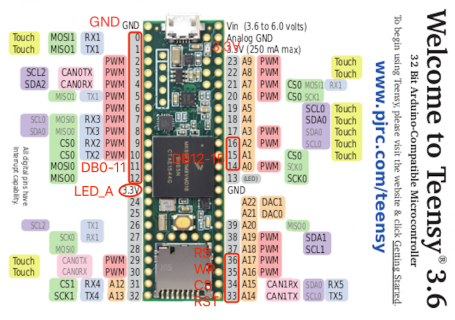
But in UTFT_Demo_320x240 you have assigned CS to 3 and RST to 4.
Code:
// These 4 signals can connect to any unused digital pins
#define RS  23
#define WR  22
#define CS  3
#define RST 4

UTFT myGLCD(ILI9327, RS, WR, CS, RST);  // Remember to change the model parameter to suit your display module!
You cannot use DB_3 as 3 as well as CS and DB_4 as 4 as well as RST.
Therefore I would suggest that you alter DB_3 and DB_4. You might want to consider altering other of the DB_ pins to match your connection layout.

Thank you mate, for your guide. Now I have modified the UTFT.cpp as:
Code:
	word	dsx[] = {239, 239, 239, 239, 239, 239, 175, 175, 239, 127, 127, 239, 271, 479, 239, 239, 239, 239, 239, 239, 479, 319, 239, 175, 127, 239, 239, 319, 319};
	word	dsy[] = {319, 319, 319, 319, 319, 319, 219, 219, 399, 159, 127, 319, 479, 799, 319, 319, 319, 319, 319, 319, 799, 479, 319, 219, 159, 319, 319, 479, 479};
	byte	dtm[] = {16, 16, 16, 8, 8, 16, 8, SERIAL_4PIN, 16, SERIAL_5PIN, SERIAL_5PIN, 16, 16, 16, 8, 16, LATCHED_16, 8, 16, 8, 16, 16, 16, 8, SERIAL_5PIN, SERIAL_5PIN, SERIAL_4PIN, 16, 16};

the HW_Teensy3.h has been modified as:
Code:
// SET WHICH PIN DEFINITIONS TO USE HERE
// (only uncomment 1 of these 3 lines)
//
//#define PORTS  USE_B_D_PORTS
//#define PORTS  USE_C_D_PORTS
#define PORTS  USE_USER_PORTS

#if (PORTS == USE_USER_PORTS)
	#pragma message("Using user-defined pins")
	#define DB_0 0
	#define DB_1 1
	#define DB_2 2
	#define DB_3 3
	#define DB_4 4
	#define DB_5 5
	#define DB_6 6
	#define DB_7 7
	#define DB_8 8
	#define DB_9 9
	#define DB_10 10
	#define DB_11 11
	#define DB_12 12
	#define DB_13 14
	#define DB_14 15
	#define DB_15 16
and the UTFT_Demo_320x240 has been modified as :
Code:
#define RS  36
#define WR  35
#define CS  34
#define RST 33

UTFT myGLCD(ILI9327, RS, WR, CS, RST);

The wires are connected as:
Connections.png
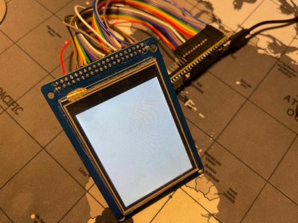
But I don't know what I missed, the screen shows nothing.
 
You haven't shown 3.3v and gnd used. I assume you have.
Other than that a picture of your setup where the connections can be confirmed.
 
Just found this.
You could try changing the model to SSD1289, which happens to be a 320X240 16 bit display.
Otherwise check and re-check your connections.
The easiest way is to disconnect and then re-connect everything. It is very easy to overlook a simple mistake when just examining wiring which refuses to work.
There is something on there about jumpers and 5v connections. Setting it to 3v might make all the difference, even though the writer said that it does not.
Thanks. I have rewired, tried SSD1289, only 3.3v connected, but still no luck...
 
Status
Not open for further replies.
Back
Top