Teensy 4.1 PWM on pin 53

Status
Not open for further replies.
Hello,

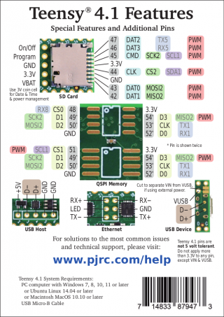
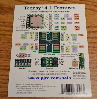
I want to use pin 53 as a PWM output on the back side of the Teensy 4.1 (I use all other pins, so changing is not an option). This should be possible according to the pinout reference card. But it doesn't work.

In C:\Program Files (x86)\Arduino\hardware\teensy\avr\cores\teensy4\pins_arduino.h, line 112, I find:

#define digitalPinHasPWM(p) ((p) <= 15 || (p) == 18 || (p) == 19 || ((p) >= 22 && (p) <= 25) || ((p) >= 28 && (p) <= 31) || (p) == 33)

So pin 53 is not there. My question is if this is a mistake on the pinout reference card, or in the line above.

If pin 53 has PWM, is there a way to enable it?

Thanks!
 
Can you show us what you're doing now? Pin 53 does support PWM, but it's hard to say what might be wrong unless we see your code. Pin 53 can do PWM. It's on one of the iMXRT processor's flexPWM modules.
 
Can you show us what you're doing now? Pin 53 does support PWM, but it's hard to say what might be wrong unless we see your code. Pin 53 can do PWM. It's on one of the iMXRT processor's flexPWM modules.

Yes, here's is the essence of the code:

analogWriteResolution(11); // 0-2047
pinMode(53, OUTPUT);
analogWriteFrequency(53, 29296.875);
analogWrite(53, 1024);

This code does not produce a PWM output.
 
Since you're using "all pins", you may have a conflict in pin usage. Pins cannot all be configured completely independently. For example, pins associated with a single flexPWM or other module share clock frequencies, etc. I don't have a T4.1 with pin 53 available, so for now I can only make suggestions.

- make a very simple sketch that configures PWM on pin 53 only
- start with default resolution and frequency
- if you can get a PWM signal with defaults, move on to experiment with resolution and frequency settings
- if PWM works in your simple sketch, but not in your larger sketch, you may have a pin/configuration conflict
 
Ok, I tried:

void setup() {
pinMode(53, OUTPUT);
//digitalWrite(53, HIGH);
analogWrite(53, 100);

}

void loop() {
}

Does not produce a PWM output. I also tried just to set the pin high, and it does so, so the output is working properly.
From the home page it says "FlexPWM3 Module0 - Controls PWM pin 53", so pin 53 should be decoupled from other PWM signal.

As I mentioned above, the macro "digitalPinHasPWM(p)" in pins_arduino.h will return false on p=53. Can this be the cause to the problem?
 
I don't think digitalPinHasPWM() is a problem. That macro defines standard Arduino PWM pins, and it's not used at all in the Teensy4 core.

If you look at startup.c, prior to calling pwm_init(), function configure_external_ram() is called for Teensy 4.1. This is speculation on my part, but it may be that pin is somehow assigned to FlexSPI for use with external ram, and something needs to be reconfigured to make it available for PWM. You could try commenting out that function call, but if that doesn't work, I'll have to let someone with more knowledge of T41 take it from here.
 
Ok, I tried:

void setup() {
pinMode(53, OUTPUT);
//digitalWrite(53, HIGH);
analogWrite(53, 100);

}

void loop() {
}

Does not produce a PWM output. I also tried just to set the pin high, and it does so, so the output is working properly.
From the home page it says "FlexPWM3 Module0 - Controls PWM pin 53", so pin 53 should be decoupled from other PWM signal.

As I mentioned above, the macro "digitalPinHasPWM(p)" in pins_arduino.h will return false on p=53. Can this be the cause to the problem?

Seems like 53 is not working for PWM I just tried it but moved you analogWrite to the loop and used the freqMeasure library - hooked pin 22 up to 53. But with that said I tried pin 51 and it worked without an issue:
Code:
4482.29
4482.29
4482.29
4482.29
4482.29
4482.29
4482.29
4482.29
4482.29
4482.29
Heres the sketch I used:
Code:
/* FreqMeasure - Example with serial output
 * http://www.pjrc.com/teensy/td_libs_FreqMeasure.html
 *
 * This example code is in the public domain.
 */
#include <FreqMeasure.h>

void setup() {
  Serial.begin(57600);

  pinMode(53, OUTPUT);
//digitalWrite(53, HIGH);
//analogWrite(21, 50);

  FreqMeasure.begin();
}

double sum=0;
int count=0;

void loop() {
  analogWrite(51, 50);
  if (FreqMeasure.available()) {
    // average several reading together
    sum = sum + FreqMeasure.read();
    count = count + 1;
    if (count > 30) {
      float frequency = FreqMeasure.countToFrequency(sum / count);
      Serial.println(frequency);
      sum = 0;
      count = 0;
    }
  }
}

EDIT Actually think card may be wrong - PWM is on D3 - pin 54
 
Last edited:
Actually think card may be wrong - PWM is on D3 - pin 54

@mjs513, I think you're right. I just modified the simple sketch to use pin 54 rather than 53 and I get a PWM signal on pin 54.

See the code below from cores\Teensy4\pwm.c. The last line says "53" in the comment, but it's at index 54 of the table. If you call analogWrite(53,x) or analogFrequency(53,y), nothing will happen because index 53 in the table is not defined for PWM.

Code:
#ifdef ARDUINO_TEENSY41
	{0, M(1, 0), 0, 0},
	{0, M(1, 0), 0, 0},
	{1, M(2, 3), 1, 6},  // FlexPWM2_3_A  36  // B1_00
	{1, M(2, 3), 2, 6},  // FlexPWM2_3_B  37  // B1_01
	{0, M(1, 0), 0, 0},
	{0, M(1, 0), 0, 0},
	{0, M(1, 0), 0, 0},
	{0, M(1, 0), 0, 0},
	{1, M(1, 1), 2, 1},  // FlexPWM1_1_B  42  // SD_B0_03
	{1, M(1, 1), 1, 1},  // FlexPWM1_1_A  43  // SD_B0_02
	{1, M(1, 0), 2, 1},  // FlexPWM1_0_B  44  // SD_B0_01
	{1, M(1, 0), 1, 1},  // FlexPWM1_0_A  45  // SD_B0_00
	{1, M(1, 2), 2, 1},  // FlexPWM1_2_B  46  // SD_B0_05
	{1, M(1, 2), 1, 1},  // FlexPWM1_2_A  47  // SD_B0_04
	{0, M(1, 0), 0, 0},  // duplicate FlexPWM1_0_B
	{0, M(1, 0), 0, 0},  // duplicate FlexPWM1_2_A
	{0, M(1, 0), 0, 0},  // duplicate FlexPWM1_2_B
	{1, M(3, 3), 2, 1},  // FlexPWM3_3_B  51  // EMC_22
	{0, M(1, 0), 0, 0},  // duplicate FlexPWM1_1_B
	{0, M(1, 0), 0, 0},  // duplicate FlexPWM1_1_A
	{1, M(3, 0), 1, 1},  // FlexPWM3_0_A  53  // EMC_29
#endif
 
Positive the card is incorrect. That pin is shown as EMC_29 which is a PWM pin for FlexPWM3_0_A and not pin 53
 
Yes, and good news for OP, if he specifies pin 54 rather than 53, he can get what he wants.

Don't blame the op - several had a hand in reviewing the back of the pinout card, including me, and the Core files but we all missed it. More than likely because those pads were really meant for the PSRAM or Flash chips and that was our primary focus. The cards will get updated eventually. Think you are the first person that ever used those pads for anything other than PSRAM or FLASH so was a good find going forward.
 
Ultimately any error on the pinout card is my fault. I alone am to blame!

I will update the card and get new ones printed soon.

Whether we use up or discard / recycle the remaining erroneous cards still remains to be decided. Many existing cards are already at distributors. We don't have any mechanism for recalling & replacing documentation cards which are already in distributor stock.
 
Here https://github.com/luni64/TeensyTimerTool/wiki/Avoid-PWM-timer-clashes a sketch which reads this information out of the core files. For your convenience the page also shows the output for T4.1, T4.0 TMM and T36 in lists sorted by Pin, GPIO and PWM timer.

Forgot all about that sketch its been so long since I last used used it. Thanks for the reminder.

Frank B said:
A note on the website should be sufficient.
Think it would have to be in 2 places:
https://www.pjrc.com/store/teensy41.html#pins
and
https://www.pjrc.com/teensy/td_pulse.html
 
I'm finally updating the back side of the Teensy 4.1 card. We're getting ready to order another batch of cards this week, to start shipping probably mid-October.

Here's the back side with pin 54 PWM fixed. System requirements now mentions Windows 11.

t41cardupdate.png
 
Good Morning all,

The PWM stuff here is sort of interesting...
Note: Should probably update cores\teensy4 (line 83) the comments shows 53 as pin number but should be 54...

The interesting thing is that 53 COULD be a PWM pin, but it has the same FLEXPWM signal as is on pin 43 (In the SD Card adapter).

There are a few others that similar thing with some other pins as well)...
Not sure if it would be worth it in future to allow these duplicates to be used, with the understanding that you can use Pin A or Pin B but not both for Analog...
SortOf like SerialX.setRX(...) ?

But on T41 there are I believe 5 pins like this in the memory region.
 
@Paul - See that you already updated that Comment...

At times I wonder if we should allow users to use these other duplicate pins, but not fully advertise them, except maybe on the PWM page..
Sort of in the same way as you show only a subset of the SPI CS pins on the card, but the SPI apis do allow us to use the other CS pins as buyer beware...

My guess is it would be as simple as changing the table in pwm.c Probably like:

Code:
#ifdef ARDUINO_TEENSY41
	{0, M(1, 0), 0, 0},
	{0, M(1, 0), 0, 0},
	{1, M(2, 3), 1, 6},  // FlexPWM2_3_A  36  // B1_00
	{1, M(2, 3), 2, 6},  // FlexPWM2_3_B  37  // B1_01
	{0, M(1, 0), 0, 0},
	{0, M(1, 0), 0, 0},
	{0, M(1, 0), 0, 0},
	{0, M(1, 0), 0, 0},
	{1, M(1, 1), 2, 1},  // FlexPWM1_1_B  42  // SD_B0_03
	{1, M(1, 1), 1, 1},  // FlexPWM1_1_A  43  // SD_B0_02
	{1, M(1, 0), 2, 1},  // FlexPWM1_0_B  44  // SD_B0_01
	{1, M(1, 0), 1, 1},  // FlexPWM1_0_A  45  // SD_B0_00
	{1, M(1, 2), 2, 1},  // FlexPWM1_2_B  46  // SD_B0_05
	{1, M(1, 2), 1, 1},  // FlexPWM1_2_A  47  // SD_B0_04
	{1, M(1, 0), 2, 1},  // FlexPWM1_0_B  48 duplicate (44) // EMC_24
	{1, M(1, 2), 1, 1},  // FlexPWM1_2_A  49 duplicate (47) // EMC_27
	{1, M(1, 2), 2, 1},  // FlexPWM1_2_B  50 duplicate (46) // EMC_28
	{1, M(3, 3), 2, 1},  // FlexPWM3_3_B  51  // EMC_22
	{1, M(1, 1), 2, 1},  // FlexPWM1_1_B  52 duplicate (42) // EMC_26
	{1, M(1, 1), 1, 1},  // FlexPWM1_1_A  53 duplicate (43) // EMC_25
	{1, M(3, 0), 1, 1},  // FlexPWM3_0_A  54  // EMC_29
#endif
Assuming I edited table correct it should work for example either pin 48 or pin 44... In this case I think that if tried to use both, the would both output using the same frequency/duty...

Is this something I should try out?
 
For the Arduino analogWrite() function, I really need to say no to supporting the duplicate pins. I want to keep it simple. My main concern is people do share code. When others reuse that code, their expectations come from the simple pinout documentatoin and the simplicity of Arduino analogWrite().

I would like to (in my dream world of so many more hours in every day) create APIs similar to IntervalTimer to access the more advanced timer features. I want those sorts of APIs designed around user goals rather than hardware specifics. For the FlexPWM timers, that might look like 3 classes, for advanced PWM (half / full / 3-phase bridge driving w/ deadtimes, etc), for input capturing, and maybe another for non-PWM waveform synthesis. Those libraries would be more than just a thin layer on top of the timers. They would integrate with DMA and have circular buffers and probably provide callbacks or some other way to use them without rapid polling. Also in my dream world is plenty of time to write good web pages to fully explain how to use them....

But so many other APIs are so much more important. After we get MSC & MTP fully integrated, probably the next most important project is the Wire library. We really need a non-blocking API with completion callbacks (not called from interrupt context, eg use EventResponder), where transactions like write, read, write-then-read (with caller allocated buffers of any length) go onto a queue and are executed interleaved with traditional Wire library blocking access.
 
Status
Not open for further replies.
Back
Top