Need a code to use the Teensy 4.0 board to supply 6 square waves using the PWM ports

Status
Not open for further replies.
Hi Everyone,
I am currently working on a project where I need to supply 6 square waves to 6 different IR Emitters simultaneously at different frequencies ( namely 600 Hz,800Hz,1000Hz,1200Hz,1400Hz,1600Hz ), all at a 50% duty cycle.
I have ordered the Teensy board 4.0 as someone on stack exchange suggested that it would be useful.
But I do not know how to program it according to my requirements.
I am fairly new to electronics background and have no clue about the code, it is a part of my project, so I need some help.
Could someone help me with the code or send me some examples that I could refer to and get help from ?

All the help will be really appreciated. I have been stuck on this for a while.
Thank You So Much!

Sincerely,
Devansh Shukla
dshukla@g.clemson.edu
 
When you have your Teensy 4.0 board, you need to install the Arduino IDE, and then TeensyDuino. You will find instructions on pjrc.com. Once you have the software installed, you will be able to build and run programs on Teensy. Do some tutorials, starting with the "blink" program, to blink an LED. You can read about all of this in the tutorial (link below). People here will help you when you have questions, but you should start by doing some work on your own, so you're not just asking for a solution.

https://www.pjrc.com/teensy/tutorial.html
 
Thank You So Much! I ordered the teensy 4.0 board today. I will have a look at the tutorial link and start working on it. I will ask any questions over here if I face any problems. I am from a biology background, so I am struggling with it. Thank You!
 
Hi @PaulStoffregen,
So I received my Teensy 4.0 board today, and I modified and tried to run the code example for generating square waves, which you had sent above. But I am getting an error such as "Serial Port not selected." Could you help me with where I am going wrong?
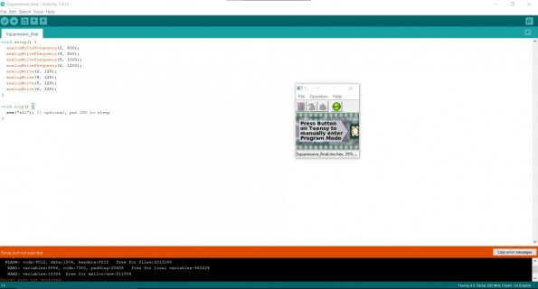
I have attached the code screenshot below.
Thank You So Much! teensy board error.jpg
 
First, by far the most common problem is charge-only cables. They look like normal USB, but have only 2 wires for power, no wires for data.

There are 2 ways you can get your code onto Teensy, as you may have seen on the final screen of the Teensyduino installer.

If you've already compiled successfully, which I can see you have in the screenshot because Teensy Loader is showing your program on it's bottom edge status area, then all you need to do is press the pushbutton on your Teensy. If it's still brand new, the orange LED should be blinking, because the LED blink program is loaded onto every Teensy as a final manufacturing test. When you press the button, the orange LED should stop. Keep your eye on that small Teensy Loader window. It should perform the code upload the moment you release the pushbutton.

If you press the button but get no response in that small window, that's a sure sign you have a bad USB cable or other USB connection problem. Again, charge only cables are by far the most common issue.

About the error, normally you would click Tools > Port to select your Teensy. But if you have a charge only cable, nothing you do will make it appear in that menu because it Teensy can't communicate with your PC.
 
Thank You So Much, Paul! Changing the cable worked. Now I am getting the msg as "Reebot Ok" once I press the button on the board. I then uploaded my code onto the board as well. I have attached the screenshot below.
So does this mean my code has successfully been uploaded onto the board, and now I have to connect the board to my circuit?
Also, once I connect the board to my circuit, how do I run or start it?

Also, could you check my code for generating/supplying 4 square waves simultaneously and continuously at 600 Hz,800 Hz, 1000 Hz, 1200 Hz, respectively to 4 IR Emitters on my circuit, which I edited from the example that you had sent:-

void setup() {
analogWriteFrequency(2, 600);
analogWriteFrequency(4, 800);
analogWriteFrequency(5, 1000);
analogWriteFrequency(6, 1200);
analogWrite(2, 128);
analogWrite(4, 128);
analogWrite(5, 128);
analogWrite(6, 128);
}

void loop() {
asm("wfi"); // optional, put CPU to sleep
}

Is this right ?

I know I am asking you too many questions, but I have a biology background and am new to circuits, so sorry for asking you too many silly doubts.
I appreciate all your help!
Thank You So Much!
 
I cannot upload the picture, but it shows "Done Uploading" at the bottom left corner. So I am guessing the code has been uploaded on the board.
Also, any document which I could refer to which would help me make the connections to the board to my circuit?
 
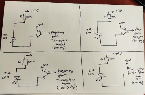
I'm more used to seeing NPN transistors drawn with the emitter pointing down, but I guess it's just a tradition. If you connect the base of the transistor directly to the output pin of the Teensy you will be clamping that digital output pin at 1 diode-drop (0.7 V or so) above ground and it will draw the maximum available current from the processor. I'm not sure what happens when you do that on four different pins at once, and I think it is not good practice. Normally there is a series resistor to limit the current, at least a few hundred ohms or so, depending what base drive you actually need. The forward voltage across an IR LED is usually about 1.2 V, and the transistor Vce saturation voltage is likely around 0.2 V so if your LED supply rail is +9V as indicated, that means you have ((9 - 1.4 V) / 100 ohms = 76 mA current through the LED. That's fine assuming the LED is rated for that current. With that power supply, it also means you'll be wasting a lot more power in the 100 ohm resistor than you are usefully putting into the IR LED, but that's just a question of efficiency, not function.
 
Last edited:
I'm not a expert with that, but the LED are run with 50% duty cycle, so I think 76mA / 2 might be ok. I think that's quite usual for IR LEDs(<- again, I'm not that sure..)
Quite possible that they will be very bright.

Perhaps try to find the datasheet of the LEDs. It should answer the question of max mA, ( may be for pulsed mode, too)

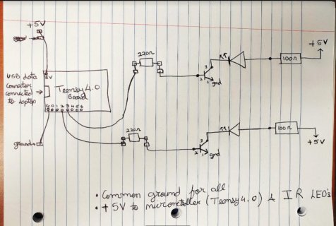
+ I would add a restor between the teensy pins and the transistor.
 
Last edited:
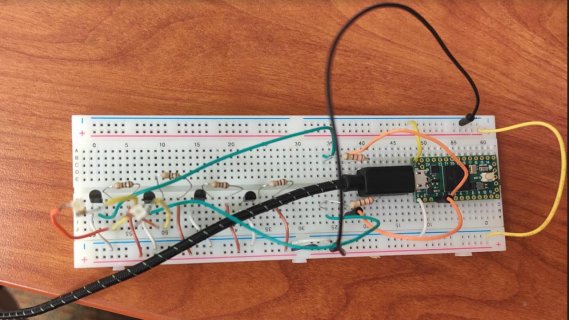
So, as suggested by Frank and JBeale, I made the changes to my circuit and connected it. But I did not get any response to it. The IR LEDs were not blinking at all. The power supply showed that the microcontroller was drawing some current, but the IR LEDs were not blinking. For the time being, I had connected only 2 IR LED's just at pins 2 and 4 of the teensy board.
I have attached the code, the schematic diagram of the new circuit, and the breadboard connection diagram.
Could someone please help me out? Where am I going wrong, please?

The code compilation was successful, and also the code was successfully uploaded onto the microcontroller.
Port "COM5 SERIAL(TEENSY 4.0") was selected.

Code:
void setup() {
analogWriteFrequency(2, 600);
analogWriteFrequency(4, 800);
analogWriteFrequency(5, 1000);
analogWriteFrequency(6, 1200);
analogWrite(2, 128);
analogWrite(4, 128);
analogWrite(5, 128);
analogWrite(6, 128);
}

void loop() {
asm("wfi"); // optional, put CPU to sleep
}teensy board connection schematic diagram 4.0.jpg

teensy 4.0 breadboard connection.jpg


Thank You So Much!!!!
 
Code:
The IR LEDs were not blinking at all.
devanshshukia:
If the LED's are truly IR how would you expect to see them blinking?
Most IR LED's emit in a spectrum below human vision so there is nothing you can do to "see" them blink, especially at 600 and 800 Hz.
If they were red LED's like the one on the teensy, they would just glow dimly.
About the only thing I could suggest is to look at the signals with an O'scope to make sure they are working.

Regards,
Ed
 
Or replace a IR LED with a visible one. But you'll see a constant light, the blinking is too fast for the eyes...

However. I think as a biologist, you know all that :) Sorry
Have you double-checked the connections?

p.s. the connections on your foto are very very unreliable. You have to solder pins to the teensy
 
Last edited:
You can use the inbuilt LED on PIN13 as indicator.

analogWriteFrequency(13, 10);
analogWrite(13, 128);

But note, it will blink fast - there is a lowest prossible frequency (I don't know what the lowest possible frequency is)
You can add the lines above to your program. If you see the fast blink, it works.
 
Hi sbfreddie, so I know IR LEDs cannot be seen through the human eye and so I used my cell phone camera to see if they were blinking. I also used an oscilloscope to see if there was a square wave seen on it or not. But they were not blinking. I did all those tests and then posted the question on the forum.
Do you suggest I should try something else as well? Do the connections seem proper to you ?
Also, should I use a 100 ohms resistor instead of 220 ohms resistor before the base of the transistor and the teensy board?

Thank You So Much!
 
Hi Frank, okay so you suggest I do solder the wire on the teensy board and then have a look at it right?
ill try that and update you guys.
Also, Do the connections seem proper to you?
Also, should I use a 100 ohms resistor instead of 220 ohms resistor before the base of the transistor and the teensy board?

Thank You So Much!
 
Also in my earlier circuit when I supplies a square waves to the IR emitters directly from the function generator, i used to supply 9 V power to the LEDs and they would blink correctly.
But now since I want to use the teensy 4.0 board to supply square waves to my emitters and JBeale mentioned that IR emitters would not require 9V to power them up, i could use a lesser current too, so i decided to power them with the same 5V supplied to the teensy 4.0 board.
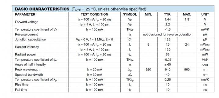
Here are the electrical characteristics of the IR Emitters.
so should 5V be enough to power them or should i return to 9V?

IR EMITTER CHAR.jpg
 
devanshshukla:
Wow that is a high current low efficiency LED.
You need to do the calculations for current thru the LED to get the brightness you want and calculate the on resistance of the transistor you are using. You also need to know the gain of the transistor to determine the base current which in turn will give you the resistance needed to drive it with the Teensy.
The Teensy 4.0 can only output a certain amount of current without damage to the pin.
I will not do these calculations for you because if I do, you will not learn anything. Perhaps one of our other kind souls will volunteer to do these calculations for you.

Regards,
Ed
 
Sure, Ed, I will do the Calculations and post them on the forum for any suggestions. Any help would be really appreciated.

Thank You So Much!
 
Status
Not open for further replies.
Back
Top