Hello!
I need some advice regarding an ethanol sensor that outputs up to 5V. Using an Arduino with 5V this is a walk in the park and there is plenty of information online.
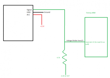
Teensy is 3.3V so I'm thinking that I need to use a voltage divider on the input pin to protect that pin from getting above 3.3V(?).
Also, what seems to be the standard here is to give the same signal wire a 4.7k res and 5V, I figure it is to give it ground if no signal.
So that begs the question. Do I give that signal wire 3.3V instead or am I missing something here?
I made a little image in paint (nice huh ).
).
Appreciate your input!

I need some advice regarding an ethanol sensor that outputs up to 5V. Using an Arduino with 5V this is a walk in the park and there is plenty of information online.
Teensy is 3.3V so I'm thinking that I need to use a voltage divider on the input pin to protect that pin from getting above 3.3V(?).
Also, what seems to be the standard here is to give the same signal wire a 4.7k res and 5V, I figure it is to give it ground if no signal.
So that begs the question. Do I give that signal wire 3.3V instead or am I missing something here?
I made a little image in paint (nice huh
Appreciate your input!


