TEE1010 - A FCB1010 rebuild with a Teensy 4.1

Status
Not open for further replies.

Expensive Notes

Well-known member
TEE1010 Part 1 - Testing - A FCB1010 rebuild with a Teensy 4.1

[FONT=&quot]I'm going to rebuild an FCB1010 into something that is more capable. To do this I am going to gut the internals and install a Teensy 4.1 and Teensy Audio card. I have delusions of it working like a bass pedal, MIDI sequencer and/or drum machine. But.... Will a 5V internal set up work with the 3.3V of the Teensy 4.1. In this short video I tested the Expression Pedals and Switches. I was mostly concerned with the 5V LED setup used for the Expression Pedals.

I am a guitar player so this foot pedal will be very helpful. Got any good ideas?

[/FONT]
 
Looks like a cool project! I've built lots of custom MIDI controllers and guitar DSP boards over the years. As far as voltages go, yeah, as I'm sure you know 5V is not safe for the Teensy 4.x.

The Teensy can take 5V in on it's VIN pin so that's nice. But if the FCB1010 circuits are designed to operate at 5V, you need to do some work. Here's my comments (you've likely already figured this stuff out but it might be helpful for readers looking at something similar).

- LEDs - these circuits likely have an 0/5V signal into an LED and current limit resistor. If you hook this up to a Teensy 3.3V output you will reduce the current and hence the brightness of the LED. However if the stock micro feeds a driver circuit like a BJT, you may not have to do anything at all. Let's assume the 5V micro output directly supplied the current to the LED circuit. You will need to replace the stock resistor with a lower valued one such that when driving by 3.3V, the current is the same as it was when driven by 5V. Instead of desoldering and replacing the old resistor, you can lower the overall resistance by connecting one in parallel with the original such that the parallel combination achieves the desired final value. This is may be easier then desoldering.

- Switches - You didn't specify in your post but I'm assuming these are pulled up to 5V, and grounded when the switch is pressed. The simple solution would be to disconnect the 5V on to the switch circuit and connect 3.3V from the Teensy instead. However that's probably not the most practical. By adding another resistor in parallel with the switch, you can create a voltage divider with the pullup such that you get 3.3V instead of 5.

Original circuit: VAL is where the switch state is measured
Code:
5V --- Rp --- SW --- GND
           |
           VAL

New Circuit:
Code:
5V --- Rp --- SW --- GND
           |
           |---VAL
           Rd
           |
          GND


- Expression inputs: the FCB1010 circuits are likely designed to go from 0V to 5V (approximately). This needs to be reduced to 0 to 3.3V. This one may be a little harder to correct as expression pedals have very different circuits and the solution must be tailored to that. Attempting to put a resistor in series or parallel with parts of the circuit may reduce the voltage to the correct range but create a non-linear behavior. Since there are very few expression pedals, you may want to simply feed the output of each expression circuit into a BJT voltage follower circuit, then use an appropriate divider on the BJT output to simply reduce the range to the 3.3V target without altering the linearity of the response.

Much of this based on speculation of the various circuits. If you have a link to a schematic for the FCB1010 it will be easier for people to offer suggestions if you want feedback on your circuit alteration ideas.
 
Thanks for your detailed explanations and hints!

I don't intend to use the 5V of the FCB1010 as I didn't want to have to worry about the Teensy having an input of 5V. I am going to replace the display with an oled that I have used with Teensys before and the MIDI out will need some resistor changes to account for the lower voltage as MIDI is current driven. MIDI.org specifies 10Ohm and 33Ohm instead of 220Ohm
Other than that the Teensy will be in charge.

The Expression pedals circuit only draws between 5.66 and 5.84 mA depending on wiper position which is way under the Teensy's maximum of 250mA.
 
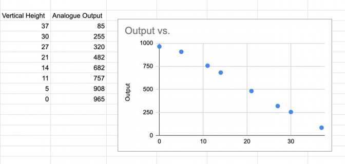
Expression Pedals: I measured the input to the Teensy vs Pedal Height and got this result.
Expression Pedal Test.jpg
The correlation was 0.9975 so everything here is good for 3.3V.
 
I want to be able to update and power the Teensy over USB once it is installed. In the past I have just used a USB cable plugged into the Teensy and had it sticking out the side of the case. Not very reliable or neat. I am thinking I need to install a USB socket into the back of the FCB 1010. I intend to use a USB B printer cable type socket because I have plenty of USB printer cable leads spare.

So...

Does the updating of the Teensys program have to be via the USB input. If I could solder some wires from the board to the USB socket it would be a lot more robust. If not I am assuming the USB connector of the Teensy would best be secured in some way. What do others do?
 
Part 2 - Choosing the Pin Connections

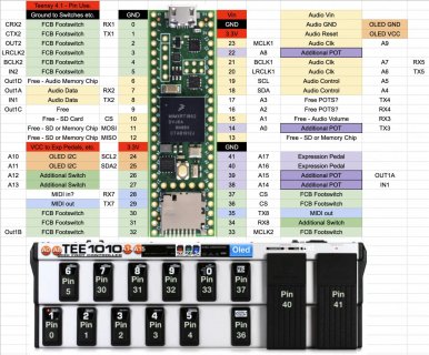
[FONT=&quot]In this Video I explain which pins I am using to connect the Teensy 4.1 to other electronics.


If you don't want to watch the video here are the pins I decided to use:

Tee1010 Pin Planning.jpg[/FONT]
 
TEE1010 Part 3 - Modifying the Insides - A FCB1010 rebuild with a Teensy 4.1


In this Video I explain how I modified the inside electronics. You can tell by the soldering and general construction that I am more of a programmer!


[FONT=&quot]TEE1010 Part 4 - Simple Mono Synth Software - A FCB1010 rebuild with a Teensy 4.1[/FONT]
[FONT=&quot]
[/FONT]
[FONT=&quot]I'm am rebuilding a FCB1010 into something that is more capable. To do this I have gutted the internals and installed a Teensy 4.1 and Teensy Audio card. I have delusions of it working like a bass pedal, MIDI sequencer and/or drum machine. [/FONT]
[FONT=&quot]
[/FONT]
[FONT=&quot]In this Video I explain how I programmed a simple mono synth. So far it has the ability to play in various scales including a major and minor scale. I have also added latch mode and an arpeggiator.[/FONT]
[FONT=&quot]
[/FONT]
[FONT=&quot]
[/FONT]
 
And now an attempt at Song Mode:

I recently found out about the EEProm. What a fabulous ability!

TEE1010 Part 5 - Song Mode - An FCB1010 rebuild with a Teensy 4.1


I'm am rebuilding a FCB1010 into something that is more capable. To do this I have gutted the internals and installed a Teensy 4.1 and Teensy Audio card. I have delusions of it working like a bass pedal, MIDI sequencer and/or drum machine.


In this Video I explain how I included a Song Mode which allows 100 patterns of up to 32 notes to be constructed and saved on the Teensy in its EEProm. Patterns are saved in Banks which can be selected using the Foot Pedals 1-5.


TEE1010 Part 6 - Song Mode With Drums - An FCB1010 rebuild with a Teensy 4.1


I'm am rebuilding a FCB1010 into something that is more capable. To do this I have gutted the internals and installed a Teensy 4.1 and Teensy Audio card. I have delusions of it working like a bass pedal, MIDI sequencer and/or drum machine.


In this Video I explain how I included drums into Song Mode. Drum patterns in 5 different styles (and also with swing) can be selected using the Foot Pedals 6-8. There are also extra oscillators and a song count in. To vary the patterns there is a probability value for each sound.


TEE1010 Part 7 - MIDI Out - An FCB1010 rebuild with a Teensy 4.1


I'm am rebuilding a FCB1010 into something that is more capable. To do this I have gutted the internals and installed a Teensy 4.1 and Teensy Audio card. I have delusions of it working like a bass pedal, MIDI sequencer and/or drum machine.


A quick video showing the MIDI Notes out working. Next will be MIDI controller...


TEE1010 - Part 8 Proper Song Mode - A FCB1010 rebuild with a Teensy 4.1


In this video I show Song mode where I can link patterns together. The songs can be saved to an SD card which is inserted into the teensy 4.1 SD slot. I have also made big changes to the software as I felt it was getting unwieldy in terms of structure. The processes are still the same, just the skeleton is changed. Also, the interface is now mostly decoupled from the playing of the music so that sounds will continue as changes are being made.


A couple of smaller things:
- You can alter the drums patterns dynamically while songs are playing with an expression pedal so it sounds more natural.
- I implemented a menu system to change pedal mode.


Because there is so much change in the software structure I have only outlined the major changes, otherwise it would take forever to explain it all. Happy to answer questions or get advice...


Code:
https://github.com/ExpensiveNotes/T...0_Mod_With_Teensy4_1_2_Part_8_3_reWr ite.ino
 
TEE1010 - Part 9 MIDI Controller - A FCB1010 rebuild with a Teensy 4.1

[FONT=&quot]Back to the Future![/FONT]
[FONT=&quot]
[/FONT]
[FONT=&quot]In this video I add what I took away - MIDI controller functionality.[/FONT]
[FONT=&quot]
[/FONT]
[FONT=&quot]The main changes are: [/FONT]
[FONT=&quot]- MIDI Messages are stored individually and can be assigned to any foot switch on any bank.[/FONT]
[FONT=&quot]- A message can be CC, PC or Note on.[/FONT]
[FONT=&quot]- More flexibility as each pedal in each bank can have from 1 to 120 messages. Mind you there are only a total of 120 messages possible, so why you would want to assign 120 to one foot switch is beyond me. But you can![/FONT]
[FONT=&quot]- 20 different Expression Pedal assignments, that can be used in whatever bank you want to.[/FONT]
[FONT=&quot]- Edit messages easily on the screen.[/FONT]
[FONT=&quot]- Only 8 pedals can be used. :([/FONT]
[FONT=&quot]
[/FONT]
[FONT=&quot] Happy to answer questions or get advice...[/FONT]
[FONT=&quot]
[/FONT]
[FONT=&quot]
[/FONT]
 
Status
Not open for further replies.
Back
Top