Good Morning,
I got my first Teensy 4.1 and did some basic light flashing stuff. Cool!
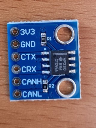
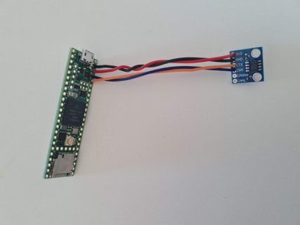
I am looking to work with Canbus and have done some reading on the various transceivers that can be connected (like MCP2515 and SN65HVD232).
Unfortunately a lot of the tutorials and other information on the internet refers to Arduino which labels pins differently.
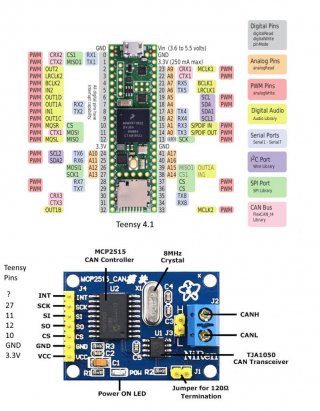
I am looking for which pins on the Teensy 4.1 are the Canbus Tx and the Canbus Rx - this doesnt appear to be on the Quick Reference card? (The quick reference card doesn't tell me but I think the light pink boxes relate to canbus pins?)
The MCP2515 board is different again. It has pins:
INT (????)
SCK (SPI Clock)
SI (MOSI - Master slave in)
SO (MISO SPI Master in Slave out)
CS (Chip select)
GND (Ground)
VCC (Power (5v?))
Can anyone tell me which pins on the Teensy 4.1 these pins should be connected to?
Thanks heaps.
Al
Last edited:


