I am designing a custom carrier board for the Teensy Micromod that will be powered by a USB-C charger IC. The charger's output voltage (2.5V~4.2V) is sent to 3.3V switching regulator and a 1.8V LDO.
I am going to attempt to explain what I tried, knowing that I am wrong somewhere. First some background. The Teensy 4.x requires a specific startup sequence, where VDD_SNVS_IN is powered before all other power inputs (with the exception that USBx_VBUS can be powered first, as it is independent).
- Here is a post that explains the startup sequence.
- Here is an animation of the startup sequence.
- Here is a page on using external power with the Teensy 2.0
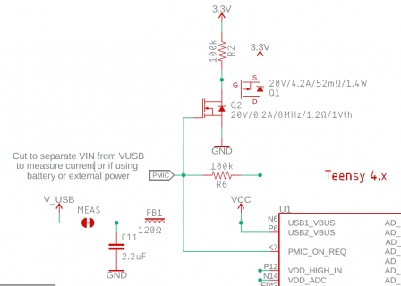
As I have external 3.3V power, I don't need to rely on step#2, where the internal USB voltage regulator turns on to create voltage for VDD_SNVS_IN. As such, I can cut the MEAS trace on the Teensy MicroMod. Note that "VCC" is just a test point.

On the ATP, V_USB (5V) is sent into a buck-boost converter (U5) which creates the 3.3V bus. I need to disconnect that and connect the output of the charger to the buck-boost converter instead. To do that, I removed the fuse (F2) and cut the BYP jumper. Then I jumped the charger output to VIN. This powers the Teensy just fine, but doesn't allow it to be programmed.

Note that there is a difference between how the Teensy 4.1 and MicroMod uses the PMIC line to release 3.3V to the processor's power input pins (Step-6). In the Teensy 4.1, the PMIC line is routed to the enable pin of the 3.3V regulator. In the MicroMod, PMIC turns on a MOSFET (Q2 & Q1) that presents 3.3V to the processor's power input pins. In either case, 3.3V reaches VDD_SNVS_IN, then PMIC releases the 3.3V to the rest of the processor's power inputs.
So that all appears to be working well. I can see the Teensy run the blink LED example.
Now the problem. When I connect a USB cable to program the Teensy, it is no longer recognized as a port. As it stands, the input to the internal USB regulator (USB1_VBUS) is left floating. Perhaps this needs 5V for the programming port to show up? If so, is there a better way to do that than a buck converter (as the USB-C wall wart can get up to 9VDC). If USB1_VBUS needs powered, what voltage range is acceptable? If 3.3V is acceptable, then I could place the MEAS jumper back to allow V_IN (3.3V) to reach USB1_VBUS (however, for some reason, that doesn't work).
Also, when I start to use my own 3.3V regulator, can I just tie the EN pin on, or do I need to hook up 3.3V_EN, as shown on the ATP shield? I assume the 3.3V_EN is to allow the Teensy to shut this regulator off and power down. Something I don't need.
Thanks in advance for this awesome community!
I am going to attempt to explain what I tried, knowing that I am wrong somewhere. First some background. The Teensy 4.x requires a specific startup sequence, where VDD_SNVS_IN is powered before all other power inputs (with the exception that USBx_VBUS can be powered first, as it is independent).
- Here is a post that explains the startup sequence.
- Here is an animation of the startup sequence.
- Here is a page on using external power with the Teensy 2.0
As I have external 3.3V power, I don't need to rely on step#2, where the internal USB voltage regulator turns on to create voltage for VDD_SNVS_IN. As such, I can cut the MEAS trace on the Teensy MicroMod. Note that "VCC" is just a test point.

On the ATP, V_USB (5V) is sent into a buck-boost converter (U5) which creates the 3.3V bus. I need to disconnect that and connect the output of the charger to the buck-boost converter instead. To do that, I removed the fuse (F2) and cut the BYP jumper. Then I jumped the charger output to VIN. This powers the Teensy just fine, but doesn't allow it to be programmed.

Note that there is a difference between how the Teensy 4.1 and MicroMod uses the PMIC line to release 3.3V to the processor's power input pins (Step-6). In the Teensy 4.1, the PMIC line is routed to the enable pin of the 3.3V regulator. In the MicroMod, PMIC turns on a MOSFET (Q2 & Q1) that presents 3.3V to the processor's power input pins. In either case, 3.3V reaches VDD_SNVS_IN, then PMIC releases the 3.3V to the rest of the processor's power inputs.
So that all appears to be working well. I can see the Teensy run the blink LED example.
Now the problem. When I connect a USB cable to program the Teensy, it is no longer recognized as a port. As it stands, the input to the internal USB regulator (USB1_VBUS) is left floating. Perhaps this needs 5V for the programming port to show up? If so, is there a better way to do that than a buck converter (as the USB-C wall wart can get up to 9VDC). If USB1_VBUS needs powered, what voltage range is acceptable? If 3.3V is acceptable, then I could place the MEAS jumper back to allow V_IN (3.3V) to reach USB1_VBUS (however, for some reason, that doesn't work).
Also, when I start to use my own 3.3V regulator, can I just tie the EN pin on, or do I need to hook up 3.3V_EN, as shown on the ATP shield? I assume the 3.3V_EN is to allow the Teensy to shut this regulator off and power down. Something I don't need.
Thanks in advance for this awesome community!
Last edited:

