Serial Midi Input not working

Status
Not open for further replies.

Holzdev

Member
Hello out there, since three days I try to get serial midi to work but to no avail. So this is my last resort to get it working.
I suspect I am making a silly mistake somewhere and hope someone will spot the error. So here I go.

I am using a Teensy 4.0 but want to use a 4.1 with audio board in the end. The 4.0 is just for testing/breadboard use.
The Programm I use is the Example Input Programm on the pjrc Midi page.
The circuit I am using is the one build here https://youtu.be/l34CNfwfuIY?t=1030.
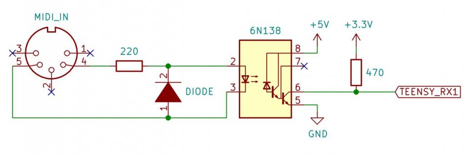
Midi_Input_Schematic.jpg
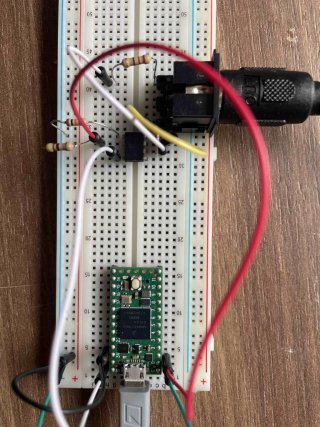
IMG_3950.jpg.
My optocoupler is labelled A6N138. The diode is 1N4148. The resistors top to bottom are: 220, 10k, 470 ohm.
My board is in usb mode Serial + Midi + Audio.
My computer is sending Midi notes to the Port via a known working interface/cable.
When running the program all I get is "MIDI Input Test" and later "(inactivity)"

I tried with teensy 4.1.
I tried different serial ports.
I tried different USB-Modes.
I read the first to pages worth of google result for "teensy serial midi".
I tried programs that seem to work for other people.
I tried downgrading the midi library to 4.3.

Any help is welcome.
 
Last edited:
Found this:-
MIDIbox Newbie
stevegs
Members
0
2 posts
Posted August 17, 2014 (edited)
This thread might be 8 years old - but here goes before anyone comes a cropper with propagation delays...


The PC900 is a digital opto-coupler - ie. if the input current to the emitting diode increases slowly, the output will snap from one state to the other when a threshold is reached. As the input current decreases, the output will snap back at a lower level - so you won't get jittering at a critical level. This is called 'hysteresis'.


Long cables (MIDI or otherwise) will slow up a signal, so a digital opto-coupler will square it up to maintain signal integrity. Or so it should...


The problem with the PC900 is it's quite slow - and even worse it takes longer to react to a decreasing current than to an increasing one (typically 2us for increasing and 5us for decreasing). Result: a skew where an original 50/50 square wave could become 60/40.


MIDI runs at 31.5kBd, ie. the time for one byte is typically 300us - so with the stop and start bits, each bit is only 30us. A 3us skew is 10% of this, so if you daisychain several MIDI devices together, data arriving at the last risks being corrupted. If the PC900's rise and fall times were the same, there wouldn't be a problem - nobody would notice a delay of milliseconds, let alone microseconds!


The 6N138 isn't digital at all. It's a simple linear Darlington coupler, ie. the output current is (roughly) proportional to the input current. This is translated to a voltage by your pull-up resistor (R6). So you risk ringing, jitter and all sorts of signal corruption problems!


You need a fast digital optocoupler, such as the HCPL2200. The rise and fall times are much shorter (typically 160ns and 180ns respectively), so there is negligible skew.


Although the maximum cable length in the MIDI spec. is 15m, I've successfully sent a signal down a 100m drum of cable as a trial before using MIDI in our theatre as a lighting control signal - the distance involved there is about 40m.


HTH


Steve G-S

Edited August 17, 2014 by stevegs
Not sure if it helps. I wonder if the 470R is a bit low.
 
Lower that 220R a bit. And try various alternative to that 470R Or just use a faster optocoupler?
 
From your photo it looks like there is a 10K(?) resistor from pin 5 of the optocoupler to GND?

Paul
 
I just checked an old project of mine. My 6N138 opto worked fine with the default 220R as drive limiter and 470R as the receive side.
 
I just checked an old project of mine. My 6N138 opto worked fine with the default 220R as drive limiter and 470R as the receive side.

Hi Tschrama, thank you. Maybe my opto is broken.
I ordered a few new ones and a HCPL2200-300e and the capacitor from the schematics just to be sure. But that's a stretch...
 
Hi Paul,
yes. I did try that. Just before the "Basic Usage" headline on the midi page it is stated that a 10k resistor might be needed there.

It states: Many work with pin 7 unconnected, but some may require a 10K resistor from pin 7 to ground.
You have a 10K resistor from pin 5 to GND. The RX line will not be able to appear LOW to the Teensy with a 10K resistor there.

Paul
 
Nice catch Paul. Pin 5 is now connected to ground and pin 7 is connected to ground with the 10K resistor. Sadly no change in behaviour :(
 
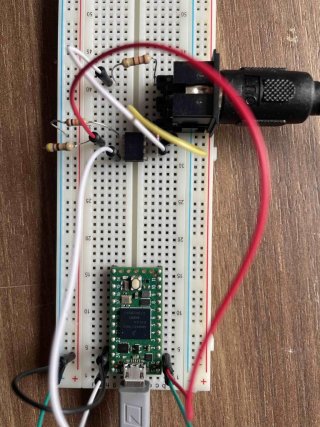
Changed back the 470 for the 3.3k Resistor. Pin 7 is now wired with 10K to ground. Pin 5 is wired to ground.
Tested two different input devices. Nothing.
IMG_3950 2.jpg
 
I'm not sure. I have a multimeter but am not sure what you want me to do. Im sorry, I'm more of a software guy so measuring hardware is new to me.
If you walk me through it I should be able to.
 
I ordered some things to better troubleshoot the problem. Some resistors and capacitors and solder breadboard as well as crocodile clamps for my multimeter. Hopefully I will be able to get things going. Thank you all very much for your input und suggestions. Things should arrive in the next days and I will keep this thread postet.
 
I have my multimeter set up to measure up voltage between opto pin 2 and din pin 4. I thought I would see something here while sending midi messages. Or won't I be able to see something with a simple multimeter?
 
The signal will be too fast. But if you put 5v DC at the opto coupler input, tell us what you see at the ouput. And if you gnd the input?
 
So I put 5v from Teensy to pin 8 on the optocoupler. I put my multimeter between pin 6 on the opto and ground on the teensy. My multimeter is set to measure 200v AC. The moment I plug in the usb it reads 0.2. Same with the multimeter between pin 5 (gnd) and teensy ground.
If I put the multimeter to measure DC between 200mv and 2000mv it reads between -1 and 0.01 which does not make sense for me.
 
Grounding the input means connecting it to ground (0V normally). Gnd is short for ground
 
Status
Not open for further replies.
Back
Top