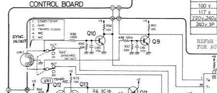
Hi All,
I found here and there the schematics to connect DIN-5 IN and OUT --> this si clear and working very well
But what if I want to connect 2 small jacks to create a clock in and another for out ? (idea is to sync without the midi din-5 ports, as in many hardware setups)
How do I connect these jacks to a T4.0 for example ... no directly I guess ?
(yes you got it, I am not an electronic engineer)
Thanks,
F


