Hi Foxhood,
Thanks for suggesting the signal levels. I verified the data sheet and it said that anything >.5V was a high. So, I think we're good there.
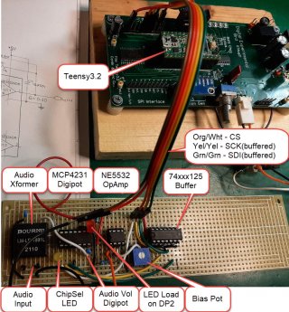
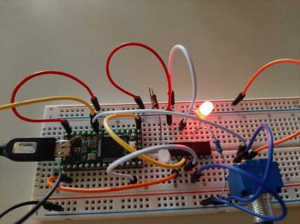
From your forest comment, I decided to strip the program down to just the Teensy and the MCP41xx digipot code, but except for the chip select, I can't get even the simplest function (on-board LED) to work.
Features:
1. I've got an LED on the CS line - that works
2. Digipot Reg0 is adjusts the intensity of/for an LED
3. Digipot Reg1 adjusts the input to an op-amp
4. A pot input into A14 (phy pin 33) used to control both registers concurrently
5. Then added short code to control the on-board pin 13 LED using the same anal-pot. Even that doesn't work!
Both the LED and the op-amp input are dependent on the manual pot input.
I know the pot varies properly - I can measure at the A14 input
SerMon does not work
And I'm getting no response from the LED. And yes, it is wired in correctly.
Obviously, I'm doing silly, stupid stuff.
New, streamed-lined script attached.
Thanks,
Dave
I'm not seeing a way to attach my latest sketch file so I've embed the script here:
--------------------
//Program for the Prototype BreadBrd Experiment - Reading the Analog Pot Values and controlling digipots
#include <SPI.h> //SPI Control library
void spi_cs();
int ledPin = 13; // the built-in LED
int PotVal;
int PotValSave;
//=========== DigiPot Write & Read =================
//Define the Global CSAddressing lines and Register Writes for the DigiPots
const int CSA0 = 0; //CS Addr0/A0 (LSB). Teensy: D0
const int CSA1 = 1; //CS Addr1/A1 Teensy: D1
const int CSA2 = 2; //CS Addr2/A2 Teensy: D2
const int CSA3 = 3; //CS Addr3/A3 (MSB) Teensy: D3
//const byte ReadReg0= B00001100; //Register 0 Read command ; This may not be needed: SPI.transfer(0); is a 'read'
//const byte ReadReg1= B00011100; //Register 1 Read command
const byte WriteReg0 = B00000000; //Register 0 Write command ; Not needed for single-reg digipots: digitalWrite(pin, state); SPI.transfer(data);
const byte WriteReg1 = B00010000; //Register 1 Write command
SPISettings settingsA(2000000, MSBFIRST, SPI_MODE0);
void setup()
{
Serial.begin(9600); //Initialize the serial port to send and receive at 9600 baud
//Chip Select address lines to the 74xx154 4-to-16 line decoder chip
pinMode(CSA0, OUTPUT);
pinMode(CSA1, OUTPUT);
pinMode(CSA2, OUTPUT);
pinMode(CSA3, OUTPUT);
pinMode(A14, INPUT); //Is this needed??
pinMode(ledPin, OUTPUT);
// Flash each of the DigiPot LEDs
spi_cs(15); // This is the Parking Place Place Addr (1111) <<<<<
spi_cs(0); // Flash LED1 (CS0 Addr=0000)ON for 200ms.
delay(200);
spi_cs(15); // Turn off the CS line: Addr (1111) <<<<<
SPI.beginTransaction(settingsA); //Since we only have a single SPI settings, don't need an SPI.endTransaction();
SPI.begin(); //Initialize SPI
}
void loop()
{
// 1. Read manual pot (10-bit word) and value print to SerMon
// 2 If the new abs(potValSaved - potVal) >2 then ...
// 3. Output potValueA to digipot 1
// 4. Output potValueA to digipot 2
// 5. Delay a bit and repeat
PotVal = analogRead(A14); // read the input on analog pin A14:
Serial.print("Pot Value = "); Serial.println(PotVal); // print out the value read from the pot
if (abs(PotVal - PotValSave) > 2) {
spi_cs(0); //Sets CS Address=CS0=0000
delay(50); //Adding a delay so the LED flashes
SPI.transfer(WriteReg0); //Select to register 0 to receive value and function
SPI.transfer(PotVal); //Transfer the Resistance level value
delay(50);
SPI.transfer(WriteReg1); //Select to Register 1 to receive value and function
SPI.transfer(PotVal); //Transfer the Resistance level value
delay(10);
spi_cs(15); //Reset the CS (turn off), to the CS=15 state
Serial.println("Both Pot registers adjusted");
}
int PotValSave = PotVal;
delay (300) ; //Wait 300msec
// The following is to turn on the on-board pin 13 LED according to the pot value
int sensorValue = analogRead(PotVal); // read the value from the Pot:
digitalWrite(ledPin, HIGH); // turn the ledPin on
delay(sensorValue); // stop the program for <sensorValue> milliseconds:
digitalWrite(ledPin, LOW); // turn the ledPin off:
delay(sensorValue); // stop the program for for <sensorValue> milliseconds:
}
void spi_cs(int ChipSelect) {
//This routine is to make it easier and reduce possible Demux address coding
//errors. Here, we pass in the desired CS address and the correct CSA lines are set
switch (ChipSelect) {
case 0: //digipot: Ch1 Diver HdPh & Aux Input: 0000 = 0
digitalWrite(CSA0, LOW);
digitalWrite(CSA1, LOW);
digitalWrite(CSA2, LOW);
digitalWrite(CSA3, LOW);
break;
case 1: //digipot: Ch2 Diver Mic Input: 0001 = 1
digitalWrite(CSA0, HIGH);
digitalWrite(CSA1, LOW);
digitalWrite(CSA2, LOW);
digitalWrite(CSA3, LOW);
break;
case 2: //digipot: Pre-Amp Gain (PAG): 0010 = 2
digitalWrite(CSA0, LOW);
digitalWrite(CSA1, HIGH);
digitalWrite(CSA2, LOW);
digitalWrite(CSA3, LOW);
break;
case 3: //Digipot: LED Br: 0011 = 3
digitalWrite(CSA0, HIGH);
digitalWrite(CSA1, HIGH);
digitalWrite(CSA2, LOW);
digitalWrite(CSA3, LOW);
break;
case 4: // Pwr-Amp Bias(PAB) (future): 0100 = 4
digitalWrite(CSA0, LOW);
digitalWrite(CSA1, LOW);
digitalWrite(CSA2, HIGH);
digitalWrite(CSA3, LOW);
break;
case 5: // Tone Gen'r (On-Brd) / "FSYNC": 0101 = 5
digitalWrite(CSA0, HIGH);
digitalWrite(CSA1, LOW);
digitalWrite(CSA2, HIGH);
digitalWrite(CSA3, LOW);
break;
case 6: //digipot: Ch2 Diver HdPh & Aux Input: 0110 = 6
digitalWrite(CSA0, LOW);
digitalWrite(CSA1, HIGH);
digitalWrite(CSA2, HIGH);
digitalWrite(CSA3, LOW);
break;
case 7: // digipot: Ch2 Diver Mic Input: 0111 = 7
digitalWrite(CSA0, HIGH);
digitalWrite(CSA1, HIGH);
digitalWrite(CSA2, HIGH);
digitalWrite(CSA3, LOW);
break;
case 8: //digipot: Ch3 Diver HdPh & Aux Input: 1000 = 8
digitalWrite(CSA0, LOW);
digitalWrite(CSA1, LOW);
digitalWrite(CSA2, LOW);
digitalWrite(CSA3, HIGH);
break;
case 9: // digipot: Ch3 Diver Mic Input: 1001 = 9
digitalWrite(CSA0, HIGH);
digitalWrite(CSA1, LOW);
digitalWrite(CSA2, LOW);
digitalWrite(CSA3, HIGH);
break;
case 10: // Tone Gen'r (Ext-DigiBrd) / "FSYNC": 1010 = 10/A
digitalWrite(CSA0, LOW);
digitalWrite(CSA1, HIGH);
digitalWrite(CSA2, LOW);
digitalWrite(CSA3, HIGH);
break;
case 11: // Ext SPI Display: 1011 = 11/B
digitalWrite(CSA0, HIGH);
digitalWrite(CSA1, HIGH);
digitalWrite(CSA2, LOW);
digitalWrite(CSA3, HIGH);
break;
case 12: // (future)
digitalWrite(CSA0, LOW);
digitalWrite(CSA1, LOW);
digitalWrite(CSA2, HIGH);
digitalWrite(CSA3, HIGH);
break;
case 13: // (future)
digitalWrite(CSA0, HIGH);
digitalWrite(CSA1, LOW);
digitalWrite(CSA2, HIGH);
digitalWrite(CSA3, HIGH);
break;
case 14: // (future)
digitalWrite(CSA0, LOW);
digitalWrite(CSA1, HIGH);
digitalWrite(CSA2, HIGH);
digitalWrite(CSA3, HIGH);
break;
case 15: //The Parking Spot! : 1111 = 15/F
digitalWrite(CSA0, HIGH);
digitalWrite(CSA1, HIGH);
digitalWrite(CSA2, HIGH);
digitalWrite(CSA3, HIGH);
break;
}
}