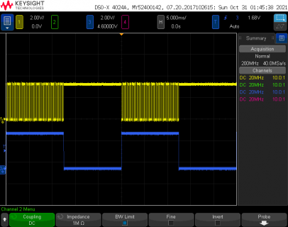
Hi,
I thought, for Teensy 4.1, attachCts() accepts XBAR pins as well as the hardware-fixed CTS pin, as mentioned for instance in:
https://forum.pjrc.com/threads/49358-T3-6-USB-Host-Bluetooth?p=278928&viewfull=1#post278928
But it doesn't work as expected when I try today, using the following code:
Both attachCts() and attachRts() return 1, meaning the attaching was successful. But transmission does not work.
The problem is unlikely from wiring or anything other than the use of pin 30. In fact, I've confirmed that everything works well when I change "#define ESPSERIAL_CTS_PIN 30" to 19 (= originally assigned CTS for Serial3) and change wiring from 30 to 19. In this case transmission works well in both directions.
I took a quick look at the source of attachCts() in Teensyduino 1.55, and found that it has some code to deal with XBAR pins. I also found that pin 30 is an XBAR pin, due the following part of HardwareSerial.cpp of Teensyduino core. I tried a few times with some other SerialX (eg Serial8) and with some other XBAR pins, but it didn't work.
I'm curious, but I could't proceed to investigate the Teensyduino code further, because I don't understand the notion of "XBAR" yet. (By the way, what is a good source to learn about XBAR, other than the IMXRT manual?)
Any comment/help will be greatly appreciated!
I thought, for Teensy 4.1, attachCts() accepts XBAR pins as well as the hardware-fixed CTS pin, as mentioned for instance in:
https://forum.pjrc.com/threads/49358-T3-6-USB-Host-Bluetooth?p=278928&viewfull=1#post278928
But it doesn't work as expected when I try today, using the following code:
Code:
#define DEBUG_MSG(...) { Serial.printf("%s(): ", __func__); Serial.printf(__VA_ARGS__); Serial.flush(); }

#define espSerial Serial3
#define ESPSERIAL_RTS_PIN 36
#define ESPSERIAL_CTS_PIN 30

void setup() {
    while (!Serial)
      ;
    espSerial.begin(115200);

    bool r;
    r = espSerial.attachRts(ESPSERIAL_RTS_PIN);
    DEBUG_MSG("espSerial.attachRts() returned %d\n", r);
    r = espSerial.attachCts(ESPSERIAL_CTS_PIN);
    DEBUG_MSG("espSerial.attachCts() returned %d\n", r);

    delay(1000);
    espSerial.print("AT+GMR\r\n");
}

void loop() {
  if (Serial.available())
    espSerial.write(Serial.read());
  if (espSerial.available())
    Serial.write(espSerial.read());
}
Both attachCts() and attachRts() return 1, meaning the attaching was successful. But transmission does not work.
The problem is unlikely from wiring or anything other than the use of pin 30. In fact, I've confirmed that everything works well when I change "#define ESPSERIAL_CTS_PIN 30" to 19 (= originally assigned CTS for Serial3) and change wiring from 30 to 19. In this case transmission works well in both directions.
I took a quick look at the source of attachCts() in Teensyduino 1.55, and found that it has some code to deal with XBAR pins. I also found that pin 30 is an XBAR pin, due the following part of HardwareSerial.cpp of Teensyduino core. I tried a few times with some other SerialX (eg Serial8) and with some other XBAR pins, but it didn't work.
Code:
const pin_to_xbar_info_t PROGMEM pin_to_xbar_info[] = {
	{0,  17, 1, &IOMUXC_XBAR1_IN17_SELECT_INPUT, 0x1},
	{1,  16, 1, nullptr, 0},
	{2,   6, 3, &IOMUXC_XBAR1_IN06_SELECT_INPUT, 0x0},
	{3,   7, 3, &IOMUXC_XBAR1_IN07_SELECT_INPUT, 0x0},
	{4,   8, 3, &IOMUXC_XBAR1_IN08_SELECT_INPUT, 0x0},
	{5,  17, 3, &IOMUXC_XBAR1_IN17_SELECT_INPUT, 0x0},
	{7,  15, 1, nullptr, 0 },
	{8,  14, 1, nullptr, 0},
	{30, 23, 1, &IOMUXC_XBAR1_IN23_SELECT_INPUT, 0x0},
	{31, 22, 1, &IOMUXC_XBAR1_IN22_SELECT_INPUT, 0x0},
	{32, 10, 1, nullptr, 0},
	{33,  9, 3, &IOMUXC_XBAR1_IN09_SELECT_INPUT, 0x0},

#ifdef ARDUINO_TEENSY41
	{36, 16, 1, nullptr, 0},
	{37, 17, 1, &IOMUXC_XBAR1_IN17_SELECT_INPUT, 0x3},
	{42,  7, 3, &IOMUXC_XBAR1_IN07_SELECT_INPUT, 0x1},
	{43,  6, 3, &IOMUXC_XBAR1_IN06_SELECT_INPUT, 0x1},
	{44,  5, 3, &IOMUXC_XBAR1_IN05_SELECT_INPUT, 0x1},
	{45,  4, 3, &IOMUXC_XBAR1_IN04_SELECT_INPUT, 0x1},
	{46,  9, 3, &IOMUXC_XBAR1_IN09_SELECT_INPUT, 0x1},
	{47,  8, 3, &IOMUXC_XBAR1_IN08_SELECT_INPUT, 0x1}
#else
	{34,  7, 3, &IOMUXC_XBAR1_IN07_SELECT_INPUT, 0x1},
	{35,  6, 3, &IOMUXC_XBAR1_IN06_SELECT_INPUT, 0x1},
	{36,  5, 3, &IOMUXC_XBAR1_IN05_SELECT_INPUT, 0x1},
	{37,  4, 3, &IOMUXC_XBAR1_IN04_SELECT_INPUT, 0x1},
	{38,  9, 3, &IOMUXC_XBAR1_IN09_SELECT_INPUT, 0x1},
	{39,  8, 3, &IOMUXC_XBAR1_IN08_SELECT_INPUT, 0x1}
#endif
};
I'm curious, but I could't proceed to investigate the Teensyduino code further, because I don't understand the notion of "XBAR" yet. (By the way, what is a good source to learn about XBAR, other than the IMXRT manual?)
Any comment/help will be greatly appreciated!


