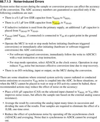
Looking over https://en.wikipedia.org/wiki/Audio_bit_depth#Quantization and found good number to keep in mind is that every additional bit of sample resolution increases the signal-to-quantization-noise ratio by 6 dB. So 12-bit resolution provides 72 dB of range, and 13-bit resolution provides 78 dB of range.
You are using an out of date browser. It may not display this or other websites correctly.
You should upgrade or use an alternative browser.
You should upgrade or use an alternative browser.
print cumulative histogram of measurements of analog pin via Teensy 4.x to serial
- Thread starter ericfont
- Start date
The ENOB formula for a perfect ADC is 6.02*bits+1.76, not just 6*bits. The rms quantization noise is sqrt(1/6)
of an LSB not 1/2 an LSB, which accounts for the extra amount.
When testing an ADC to measure effective number of bits and its close to ideal you cannot use a fixed input
voltage as the test signal since how well the converter performs would depend on how close to the centre of
a voltage band the test voltage happened to be. However if the error is several LSBs or more this becomes
unimportant and the prob. distribution becomes a useful measure of rms quantization noise.
Sampling a sinusoid and measuring the noise floor from the power spectral density plot is a method that will
work in either case, and it will show up any spurs in the spectrum too - if the signal is high purity you can
measure non-linearities too.
Using a slowly ramping voltage and then plotting a histogram (having corrected for the slope) is probably
an easier method as the signal source can be a large capacitor with bleed resistor - this is basically a least-
squares linear regression.
Ok, thanks for the valuable insight.
My original hope with the 12-bit converter is that because there is already like close to ~2-bits of noise, that then taking a ton of samples of the same held signal level could help refine the precision...and my hope was that that noise would actually help out with the measurements because that noise would actually help by causing the ADC to produce results over a range of like 4 neighboring digital numbers probabilistically around a true mean. And I ended up using a LF398 sample-and-hold IC with a 100 nF hold capacitor to keep the a steady version of the input signal for repeated measurements.
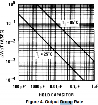
Reading your post and I'm thinking now maybe I should carefully choose a value of for the LF398 hold capacitor to deliberately give me droop rate just large enough to cover a few neighboring digital numbers over however many number of samples I'm trying to take. And it seems the LF398 datasheet provides a chart of droop rate versus hold capacitor size:

However if the error is several LSBs or more this becomes unimportant and the prob. distribution becomes a useful measure of rms quantization noise.
My original hope with the 12-bit converter is that because there is already like close to ~2-bits of noise, that then taking a ton of samples of the same held signal level could help refine the precision...and my hope was that that noise would actually help out with the measurements because that noise would actually help by causing the ADC to produce results over a range of like 4 neighboring digital numbers probabilistically around a true mean. And I ended up using a LF398 sample-and-hold IC with a 100 nF hold capacitor to keep the a steady version of the input signal for repeated measurements.
Using a slowly ramping voltage and then plotting a histogram (having corrected for the slope) is probably an easier method as the signal source can be a large capacitor with bleed resistor - this is basically a least-squares linear regression.
Reading your post and I'm thinking now maybe I should carefully choose a value of for the LF398 hold capacitor to deliberately give me droop rate just large enough to cover a few neighboring digital numbers over however many number of samples I'm trying to take. And it seems the LF398 datasheet provides a chart of droop rate versus hold capacitor size:

mborgerson
Well-known member
I believe there's a minor problem in the first line of the setup function:
pinMode(analogReadPin, INPUT);
If you're expecting good results with analog inputs, you should set up the pin with:
pinMode(analogReadPin, INPUT_DISABLE);
This shuts down the pin-keeper resistors on the T4.X that can affect inputs near the middle of the ADC range. This subject is discussed in this thread:
https://forum.pjrc.com/threads/3431...ce-and-pull-up?highlight=analog+INPUT_DISABLE
I believe there's a minor problem in the first line of the setup function:
https://forum.pjrc.com/threads/3431...ce-and-pull-up?highlight=analog+INPUT_DISABLE
Oh good to know, thanks for pointing that out... I've added a commit to my code now to fix that, thanks.


