Display to go with Teensy 4.1 and Audio Board

Status
Not open for further replies.

bolau

Active member
Hi all,

first off, I'm not a hardware guy and try to avoid cables, connectors and stuff like that as much as possible to reduce the number of things that can break when performing on stage.

In the past, I've used a Teensy 3.6 with the Audio Shield and the TeensyView display as my MIDI processor and loop station:
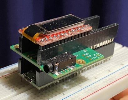
teensy_stack.jpg

Since the Teensy 4.0 supports multiple virtual MIDI ports when connected to my MIDI interface (MIO-XL), whereas the Teensy 3.6 doesn't (a bug in the USB stack), I would like to finally upgrade to a Teensy 4.0 or 4.1. I understand that I can get the new Audio board (Rev D), but what can I use as display? As far as I can see, the TeensyView doesn't support Teensy 4.x, and also I'd like to upgrade to a larger display with more pixels.

Is there any display you can recommend that works with Teensy 4.0 or 4.1 without making extra boards, power supply and so on? What's the easiest in terms of hooking up, putting it into a case with the Teensy, and so on?

This one seems to work with Teensy 3.6 with and without Audio board, but there's not pinning variant for teensy 4.x with Audio board, as far as I can see:
https://www.pjrc.com/store/display_ili9341_touch.html

Thanks for any help
Boris
 
Unfortunately, the TeensyView is the only display I can think of that is made to plop directly on a Teensy 3.x and 4.x series and work with the audio board. You would need to use the following pin assignments:

  • D/C: Pin 5
  • CS: Pin 20/A6
  • MOSI: Pin 11
  • SCLK: Pin 13

You could use a prototype board that either has another parallel row of pins where you solder in the 48 pins for the Teensy 4.1, and then solder jumper wires to an unused spot that has enough room for the display. Some that may work include:


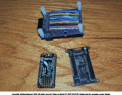
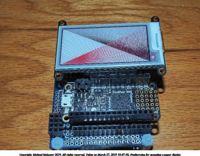
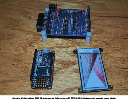
As an example of what I mean, I also play around with Adafruit Feather products (and Teensy with the feather adapter). Unfortunately some of their displays are meant to be mounted underneath the board, and it doesn't work with some boards that you can't mount things that way. So I made a converter board that swapped the pins, and it allows me to use those displays. Note, the particular prototype board would not be suitable for the Teensy 4.1/3.5/3.6 since it only has 20 rows of pins, but the ElectroCookie board above could be used.

2019-03-27-10-47-003-featherwing.jpg
2019-03-27-10-47-004-featherwing.jpg
2019-03-27-10-46-002-featherwing.jpg
 
Hi Michael,
thank you very much for your reply!

Just to be sure, the pin assignments you wrote above are meant for the TeensyView, correct? I'm trying to match that with the hookup guide. Then I guess MOSI is the same as DATA, but which would be the correct pin for RST? 15 or 2?

Using these prototype boards seems great advice, and it makes be eager to go for the bigger display. But is there a pinning for the 4.1 that's compatible with the Audio Board? Comparing the two pages reveal pin numbers that "collide" (8, 10, 11, 12, 13), at least number 8 in one of the audio rows.

If there's a good read that brings me up to speed on how to properly move my way around such pin collisions, I'd be very interested as well.

Best, Boris
 
Hi Michael,
thank you very much for your reply!

Just to be sure, the pin assignments you wrote above are meant for the TeensyView, correct? I'm trying to match that with the hookup guide. Then I guess MOSI is the same as DATA, but which would be the correct pin for RST? 15 or 2?

Yes MOSI is what Sparkfun refers to as DATA in the hookup guide.

You want pin 2 for RST, not 15 if using the audio shield. Pin 15/A1 is hooked up to the audio shield for attaching a potentiometer. While you might not use the potentiometer, the audio shield does have some resistors and capacitors on the line that might interfere with using it for reseting the board.

Using these prototype boards seems great advice, and it makes be eager to go for the bigger display. But is there a pinning for the 4.1 that's compatible with the Audio Board? Comparing the two pages reveal pin numbers that "collide" (8, 10, 11, 12, 13), at least number 8 in one of the audio rows.

If there's a good read that brings me up to speed on how to properly move my way around such pin collisions, I'd be very interested as well.

Best, Boris
I created a spreadsheet some time ago to compare Teensies and other boards:

  • https://docs.google.com/spreadsheets/d/1LSi0c17iqtvpKuNSYksMG306_FpWdJcniSRR6aGNNYQ/edit?usp=sharing
  • The first sheet of the spreadsheet attempts to list every single pin for each of the models to show how things are the same or different.
  • The second sheet of the spreadsheet lists the MicroMod pinouts.
  • The third sheet compares the Teensies at a higher level (amount of memory, speed, # of pins, etc.).
  • The fourth sheet compares the pinout of various Teensy shields.
  • The fifth sheet has some pinouts of other chips.
  • The sixth sheet compares the pinout for various microprocessors that have Adafruit feather boards, including the Teensy adapter.
  • The seventh sheet compares the pinout of various Adafruit feather wings (shields).
  • The eighth sheet gives URL links for various feather devices.
  • The ninth sheet gives various I2C devices, including the default I2C address.

Basically, for the audio shield you need to consult the audio shield page and the Teensy pinout card:

I put this page on the unofficial Teensy wiki to give an overview of pin level compatibility between the Teensies:
 
Awesome! I think I get an understanding how that works, will give it a try with the TeensyView. Thanks again!
 
One more thing after studying your pin suggestions:


According to the Audio Board pin list for Teensy 4.x, pin 20 is used for audio data. Does it make sense to move the CS pin of the TeensyView to the other option, pin 10, in that case? Or am I getting something wrong?

You are right, pin 20/A6 is used for I2S (LRCLK1 in particular). Sorry I missed that. The trouble with using pin 10 is the audio board uses that for the micro-SD card on the audio board. This means if you use it for CS for the TeensyView, the audio micro SD card will also try to do its stuff (with SPI, the CS pin is used to enable the device). So it looks like the TeensyView might not be compatible in this case (unless you can insulate pin 10 so it doesn't make contact with the audio board).
 
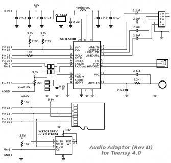
Well, I don't have to use the SD card on the audio board at all. So if I read the schematic right, I "just" need to remove the 10k resistor that connects Pin 10 to 3.3V, and not call SD.begin(10) in my code.

schematic_audio4.png
 
A thing like the WT32-SC01 but with Teensy instead ESP would be great, if it had a comparable price (and wlan).
 
Yes Frank, that would indeed be incredibly helpful. Display with onboard Teensy, SD slot and headphones out would be an amazing package...
 
Michael, thanks again for your help. It took me some time to get to the project, but it worked like a charm, TeensyView on Teensy 4.1 with audio shield :)
 
Status
Not open for further replies.
Back
Top